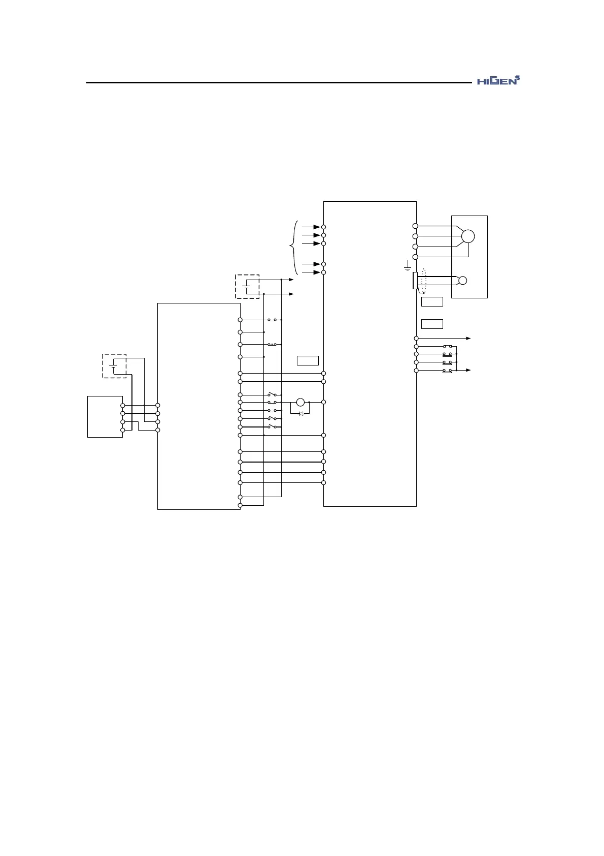
7. Connection with host controller
7-2
Connect with LS Industrial System XGT-Series position decision unit XGF-PD1A
This is an example of position control mode servo system operation.
FDA7000
24
23
1
37
RP+
FP+
HOME +5V
21
R
S
T
r
t
PRIN
PPFIN
PFIN
PPRIN
PZO
/PZO
XGT-PLC
XGF-PD1A
M
U
V
W
FG
SERVO MOTOR
CN2
CN1
AC
200 ~ 230V
50/60 Hz
+24V
GND24
+
-
+24V
CN1
34
33
8
10
DR/INP COM
EMG
COM
+24V
18
13
49
38
17
GND24
CCWLIM/PTQLIM
SVONEN
CWLIM/NTQLIM
ESTOP
GND24
24, 25
12
11
10
9
1Ry ALARM
PG
30
5
HOME COM
DR/INP
MPG A+
2
3
4
38
Manual
PULSE
DC 5V
MPG A-
MPG B+
MPG B-
5V
A
B
0V
FP-
RP-
22
DOG
28
OV+
25
OV-
26
STOP
27
+
-
+5V
VTP
COM
29
32
40
P COM
24V
39
+24VIN
20
(Note) After connecting the power, it takes about 1-2 seconds until the alarm signal leads
to normal operation. Consider this when designing the power connection sequence.
Also the alarm signal operates alarm detection relay 1Ry to turn on the main circuit
power of servo drive.
It only has the signals related to LS Industrial Systems XGF-PD1A and FDA7000 Series
(Note) The above connection is only shown in case of P07-01=27(Position control mode)
 Loading...