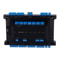
4.3 Wire Secure Door Control Unit
You can connect the terminal with the secure door control unit.
The wiring diagram is as follows.
Figure 4-3 Secure Door Control Unit Wiring
Note
The secure door control unit should connect to an external power supply separately. The suggested
external power supply is 12V, 0.5A.
4.4 Wire Fire Module
4.4.1 Wiring Diagram of Door Open When Powering O
Lock Type: Anode Lock, Magnec Lock, and Electric Bolt (NO)
Security Type: Door Open When Powering O
Scenario: Installed in Fire Engine Access
Type 1
Note
The re system controls the power supply of the access control system.
Face Recognion Terminal User Manual
14

 Loading...