5 Design and Function
5.5.2 MFE7 Process Board
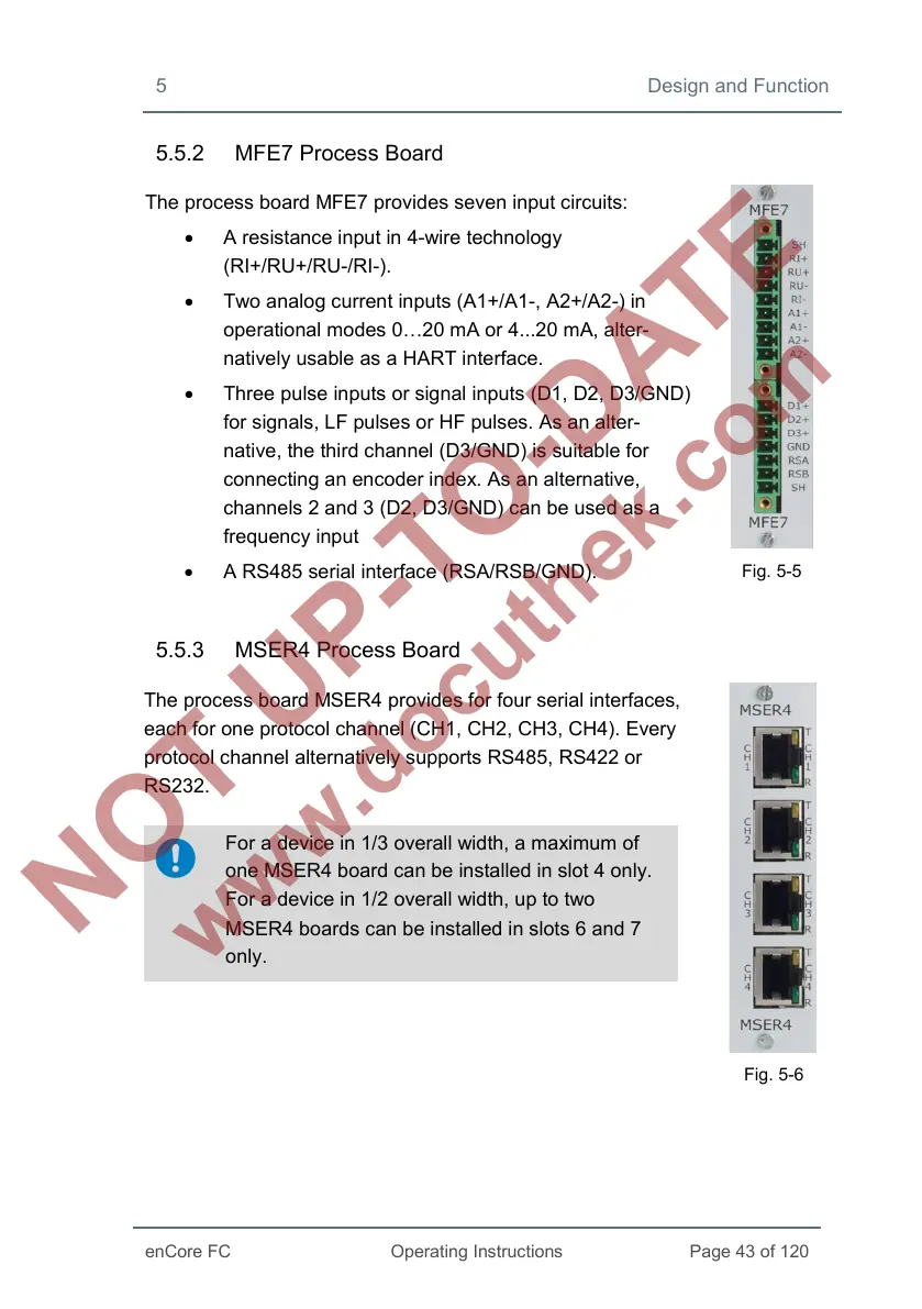
The process board MFE7 provides seven input circuits:
• A resistance input in 4-wire technology
(RI+/RU+/RU-/RI-).
• Two analog current inputs (A1+/A1-, A2+/A2-) in
operational modes 0…20 mA or 4...20 mA, alter-
natively usable as a HART interface.
• Three pulse inputs or signal inputs (D1, D2, D3/GND)
for signals, LF pulses or HF pulses. As an alter-
native, the third channel (D3/GND) is suitable for
connecting an encoder index. As an alternative,
channels 2 and 3 (D2, D3/GND) can be used as a
frequency input
• A RS485 serial interface (RSA/RSB/GND).
Fig. 5-5
5.5.3 MSER4 Process Board
The process board MSER4 provides for four serial interfaces,
each for one protocol channel (CH1, CH2, CH3, CH4). Every
protocol channel alternatively supports RS485, RS422 or
RS232.
For a device in 1/3 overall width, a maximum of
one MSER4 board can be installed in slot 4 only.
For a device in 1/2 overall width, up to two
MSER4 boards can be installed in slots 6 and 7
only.
Fig. 5-6
 Loading...


