14 NFS2-3030 Listing Document — P/N LS10006-051NF-E:F2 5/19/2022
1.8 NFPA 72 Central or Remote Station Fire Alarm System (Protected Premises Unit)
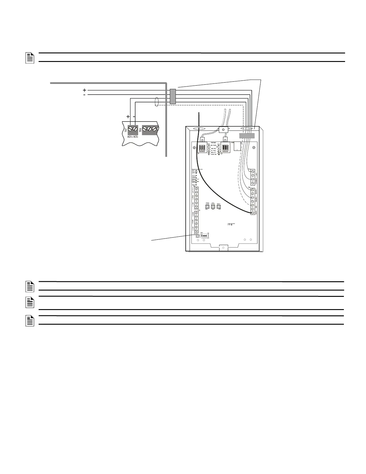
The figure below shows a typical wiring diagram for an NFPA 72 Central Station Fire Alarm System (Protected Premises Unit) or a Remote Station
Fire Alarm System (Protected Premises Unit) using the Universal Digital Alarm Communicator/Transmitter (UDACT-2) and NFS2-3030. Connect and
program the UDACT-2 according to the directions given in The UDACT-2 Listing Document.
Typical wiring of a UDACT-2 with NFS2-3030:
1.9 NFPA 72 Proprietary Fire Alarm Systems
When connected and configured as a protected premises unit with monitor and relay modules, the NFS2-3030 will automatically transmit General
Alarm, General Trouble, General Supervisory, and Security signals to a listed compatible Protected Premises Receiving Unit. A simplified drawing of
connections between the receiving unit and the NFS2-3030 protected premises unit is shown in Figures 15 and 16.
Connect the receiving unit to the protected premises unit as shown in Section 1.8 “NFPA 72 Central or Remote Station Fire Alarm System (Protected
Premises Unit)”.
NOTE: An NFPA 72 Central Station requires 24 hours of standby power; an NFPA 72 Remote Station requires 60 hours of standby power.
NOTE: This application can also be done with the TM-4 Transmitter; refer to the TM-4 Transmitter Module manual for more details.
NOTE: The following models do not comply with requirements for AC loss delay reporting when used with Central Station Protected Premises
systems: AA-30, AA-120, AA-100, APS-6R, CHG-120.
NOTE: For additional setup information for UDACT, refer to the UDACT Installation Manual.
NOTE: Set DIP switch position 4 to ON if the
UDACT-2 is the last or only device on EIA-485 line.
UDACT-2 in ABS-8RB
Solid
earth
ground
To supervised
phone lines
FACP Cabinet
EIA-485 (ACS Mode)
TB7 on control panel
Supervised and power-
limited (Class 2) EIA-485
and power wiring
3030-UDACT2.wmf
+24 VDC
non-resettable power
from main or auxiliary
power supply
+24V
Common
EIA-485+
EIA-485 -
Reference
Earth Ground
Ferrite cores
P/N 29090
Figure 14 Typical Wiring Diagram for a Central Station Fire Alarm System

 Loading...


