64 NFS2-3030 Listing Document — P/N LS10006-051NF-E:F2 5/19/2022
Network Display Mode
Network Display Mode allows the NFS2-3030 to display network events for mapped nodes.
Limitations
1. Only the following network node types can be mapped to the NFS2-3030:
• NFS2-3030
• DVC
• NFS2-640
• NFS-640
• NFS-320
• NFS-3030
• VESDA-HLI-GW
2. Read Status, Control On/Off, Disable/Enable, and Network Control-By-Event will only function for the nodes that are mapped to the NFS2-3030.
3. The number of display type nodes for the entire network is limited to a total of 25. Display nodes include NCA, NCA-2(NCA-2C for Canada
Only) , NCD, a Gateway node, or an NFS2-3030 in Network Display Mode.
Event, Mass Notification, and Drill/Alarm Signal On Mapping
The NFS2-3030 can be programmed to monitor events and initiate drill (alarm signal on for Canadian applications) on one (1) additional fire panel and
up to four (4) DVCs. Refer to “Network Mapping” on page 32.
Mapping a network node to the NFS2-3030 on the Network Mapping menu will allow the NFS2-3030 to monitor and annunciate events for that node.
Mass Notification and Drill/Alarm Signal on Mapping for the NFS2-3030 can only be changed through VeriFire Tools. Refer to the VeriFire Tools
Help File.
Panel Control Functions
Acknowledge, System Reset, Signal Silence and Drill (Alarm Signal On for Canadian applications): The NFS2-3030 has the ability to perform a
network Acknowledge, System Reset, Signal Silence and Drill/Alarm Signal On. Only the network nodes mapped to the NFS2-3030 will be affected.
Auto Silence: The Auto Silence feature also applies to any network nodes mapped to the NFS2-3030.
Print Functions
When in Network Display Mode, printing active points on the NFS2-3030 will also display any active points of any mapped network nodes.
5 Testing/Maintenance
When finished with the original installation and all modifications, conduct a complete operational test on the entire installation to verify compliance
with applicable NFPA standards. Testing should be conducted by a factory-trained fire alarm technician in the presence of a representative of the
Authority Having Jurisdiction and the owner’s representative. Follow procedures outlined in NFPA Standard 72’s section on Inspection, Testing and
Maintenance. All test and maintenance instruction codes and software necessary to provide test and inspection requirements of CAN/ULC-S536, Stan-
dard for the Inspection and Testing of Fire Alarm Systems.
5.1 Disable/Enable Points or Zones
Points or zones can be disabled for testing or maintenance via the Alter Status Menu (Refer to Section 4.3.1 on page 29).
DISABLE/ENABLE: Only the applicable command will display. Press to disable
an installed, programmed point or enable a previously disabled point.
Group Zone Disable: Disabling a general zone will disable all devices with that
zone programmed in the first zone map position.
NOTE: Use 0 (zero) ohm impedance when testing wire-to-wire faults.
WARNING: PHYSICALLY DISCONNECT RELEASING DEVICES
DO NOT RELY ON DISABLE/ENABLE SOFTWARE SETTINGS TO LOCK OUT RELEASING DEVICES. RELEASING DEVICES
MUST BE PHYSICALLY DISCONNECTED.
CAUTION: ZONE DISABLE/ENABLE
WHEN A ZONE IS DISABLED, ANY INPUT AND OUTPUT DEVICES MAPPED TO THE ZONE ARE DISABLED IF THE ZONE
IS THE POINT’S PRIMARY ZONE. (THE PRIMARY ZONE IS THE ZONE IN THE FIRST POSITION OF THE ZONE MAP.)
WHEN A DISABLED OUTPUT IS ENABLED, IT WILL BE AFFECTED BY CONDITIONS PRE-EXISTING IN THE SYSTEM.
WHEN A CONDITION EXISTS IN THE SYSTEM THAT WOULD NORMALLY TURN THE OUTPUT ON, THE OUTPUT WILL
TURN ON WHEN IT IS ENABLED.
NOTE: When an input or output associated with releasing functions is
disabled, a single supervisory trouble will be generated.
When a point associated with a FAAST device is disabled, all 5 detector
addresses programmed for the device will be disabled.
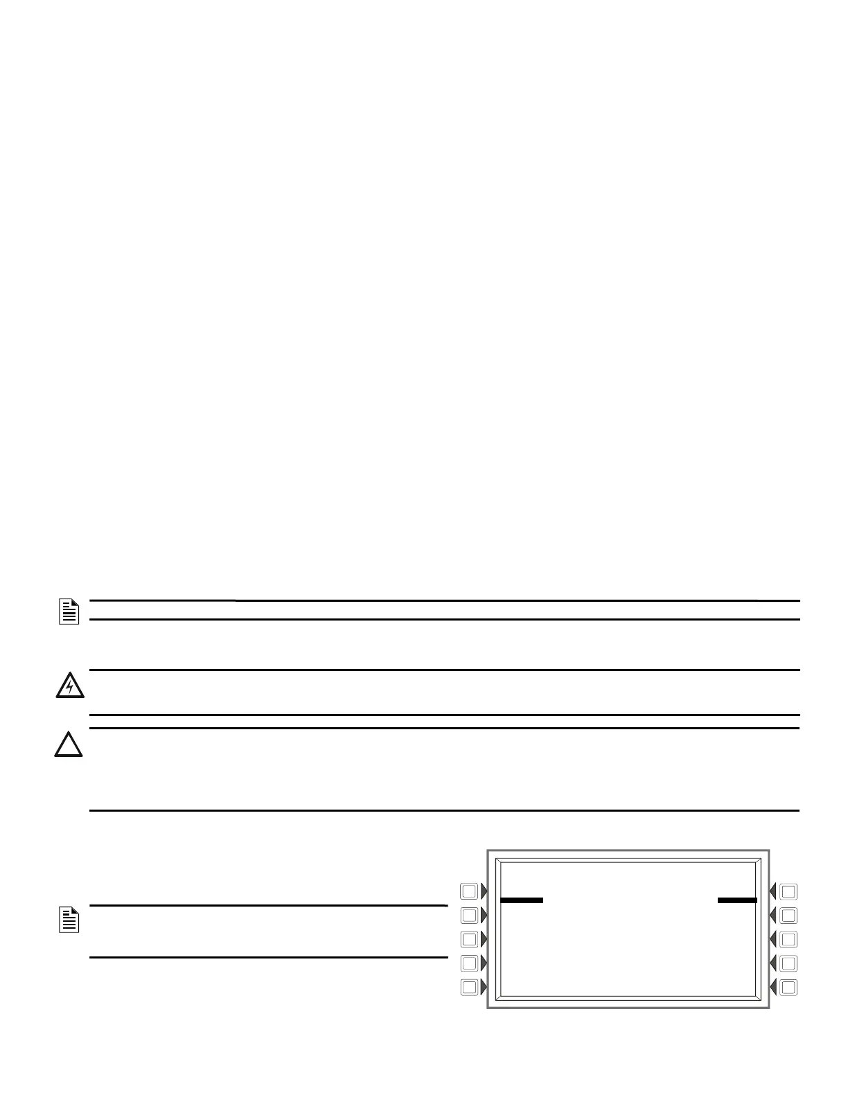
Disable/Enable Screen
LAKEVIEW GENERAL HOSPITAL
SYSTEM NORMAL
10:22:34A TUE JAN 20, 2018
DISABLE/ENABLE: N114L03D052
AUTOMATIC INACTIVE
ELEVATOR LOBBY EAST WING
FIFTH FLOOR Z005 SMOKE(PHOTO)
VALUES: 011% OF ALARM, 045% OF PREALARM
DISABLE BACK

 Loading...


