6 NFS2-3030 Listing Document — P/N LS10006-051NF-E:F2 5/19/2022
1.2 Laying Out Equipment in Cabinet and Chassis
The NFS2-3030 can be installed in CAB-3 or CAB-4 series backbox using either the CHS-M3 or CA-2 chassis. Additional rows of equipment can be
door-mounted or chassis mounted on rows below the CHS-M3 or CA-2. For additional information on the CAB-3 and CAB-4 series backbox, refer to
the CAB-3/CAB-4 Series Cabinets Product Installation Document, document number 15330. Additional components available in the CAB-4 Series
include:
• CHS-4/CHS-4N/CHS-4L - Chassis for mounting additional equipment.
• DP-DISP - Inner dress panel for covering backbox area surrounding various modules; for use in the top row.
• DP-DISP1- Inner dress panel for covering backbox area surrounding various modules; for use in top row with NCD ONLY.
• BMP-1 - Blank module plate for covering any unused module positions. Provides an additional location to mount an option board that does not
need to be accessible or visible when the door is closed.
• BP2-4 - Battery dress panel.
• DP-1B - Blank panel for covering recessed equipment in second, third, or fourth rows of the backbox.
• ADP-4B - Annunciator dress panel; for use in all but the top row.
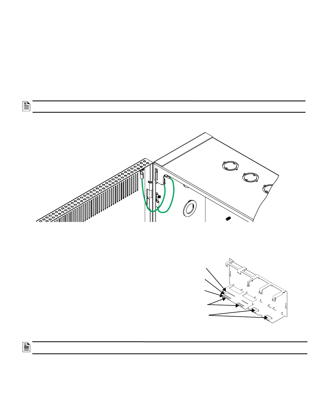
1.2.1 Earth Ground
To meet UL wiring requirements, install grounding straps on the backbox as shown below.
1.2.2 CHS-M3 Chassis
• Mounts in the top row of the cabinet
• CPU2-3030 (CPU2-3030DC for Canada only) (with or
without optional display) occupies the left half (positions 1
and 2) of the chassis.
• Can hold up to 4 layers of equipment, including option
boards and annunciators (8 boards total).
• Additional equipment can be door mounted in front of the
CHS-M3 (refer to Figure 7) or in additional chassis below.
• Proper CPU2-3030(CPU2-3030DC for Canada only)
positioning with or without a display is determined by
mounting the CPU in the proper slot and using the correct
stand-offs:
– CPU2-3030 D (with keypad and display): 1.5 inch
(38.1mm)
– CPU2-3030ND (without keypad and display: 0.25 inch
(6.35mm)
NOTE: When designing the cabinet layout, consider UL requirements regarding separation of power-limited (Class 2) and non-power-limited
wiring. Refer to1.4, "UL Power-Limited Wiring Requirements" on page 11 and your power supply manual.
NOTE: Due to the difficulty of reaching under the keypad, it may be convenient to remove the insulator from the lithium memory-
backup battery before mounting the CPU on the chassis.
Figure 4 Installing Grounding Straps
CPU Mounting
Up to four layers
of equipment
Position 1
Position 2
Position 3
Position 4
CPU2-3030(CPU2-
3030DC for Canada
only)ND Mounting
CPU2-3030(CPU2-3030DC
for Canada only)D Mounting
Mounting slot not used
with the NFS2-3030
CPU Mounting and Chassis Positions

 Loading...


