2 NFS2-3030 Listing Document — P/N LS10006-051NF-E:F2 5/19/2022
1.1 Wiring Connections, Switches and LEDs
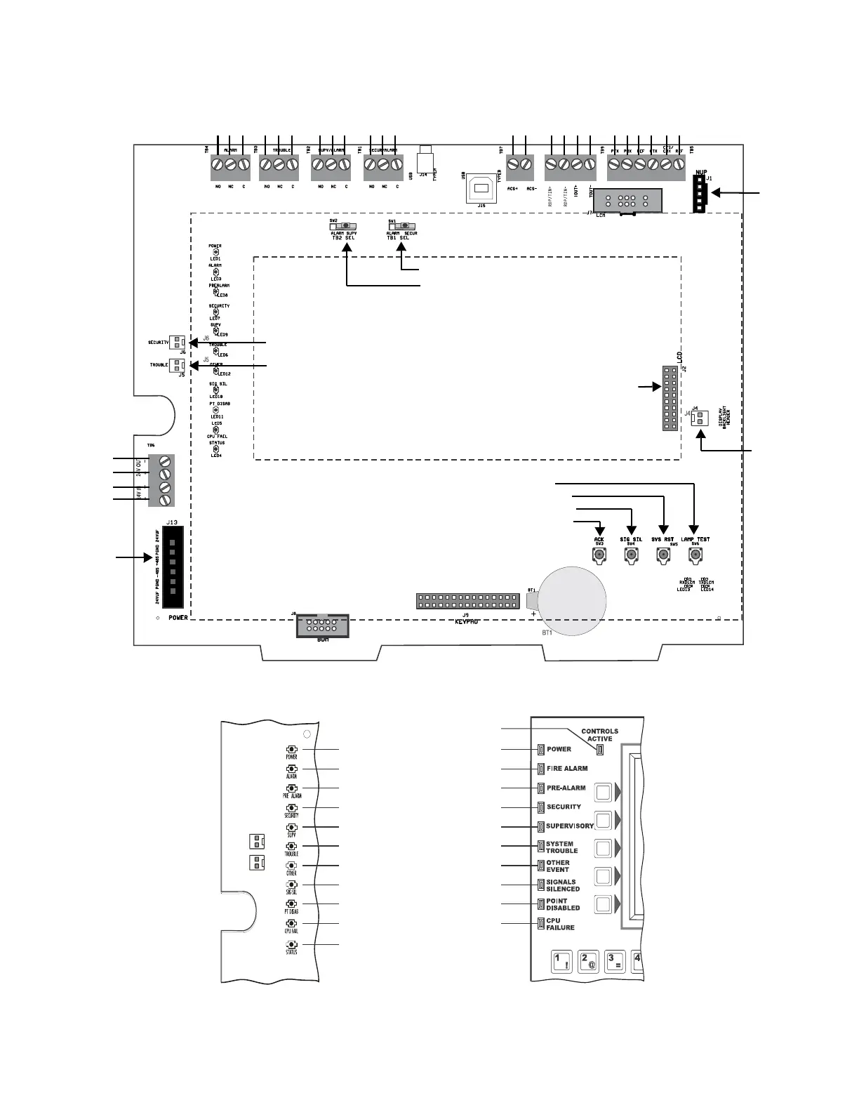
1.1.1 CPU2-3030(CPU2-3030DC for Canada only) Board Layout and Wiring Connections
TB1 - TB4:
Relays
NO NC C NO NC C
NO NC C NO NC C
*TB7:
ACS
*TB5:
Printer
TB9:RDP
+ –
+ – + –
Tin
Tout
*TB5:
PC/CRT
TX RX REFTX RX REF
TB6:
Accessory
Power
24 V
OUT
24V
IN
SW2: Supervisory/Alarm switch for TB2
SW1: Security/Alarm switch for TB1
J2
LCD
Connection
J4
Backlight
Connection
J9
Keypad
Connection
Text Fixture
No Connection
*J13
Power
Connection
SW6: Lamp Test
SW5: System Reset
SW4: Signal Silence
SW3: Acknowledge
*J7
SLC Loop Control
Module Connector
*J1:
NUP
Connector
J5: Trouble Bus Connection
J6: Security Switch Connection
J15
USB VeriFire Tools
Connection
Note: Dotted line indicates
location of optional keypad
and LCD display.
*Circuits marked with an
asterisk are supervised
for communication loss.
Lithium
Memory-
Backup
Battery
Figure 1 CPU2-3030(CPU2-3030DC for Canada Only) Wiring Connections and Switches
-
+
-
+
LEDs on Printed Circuit
Board
LEDs on Keypad
LED1 Power (Green)
Controls Active
(Green-Keypad Only)
LED3 Fire Alarm (Red)
LED8 Pre-Alarm (Red)
LED7 Security (Blue)
LED9 Supervisory (Yellow)
LED6 System Trouble (Yellow)
LED12 Other Event (Yellow)
LED10 Signals Silenced (Yellow)
LED11 Point Disabled (Yellow)
LED5 CPU Failure (Yellow)
LED4 Factory Use Only
Figure 2 CPU2-3030(CPU2-3030DC for Canada Only) LED Indicators

 Loading...


