SCS Series Manual — P/N 15712:L 7/18/16 107
Section 5: Ratings and Wiring Diagrams
5.1 Introduction
This section provides general information on the monitor modules and control modules which must be used in conjunction with the
SCS⁄SCE. This section also provides examples of possible fan and damper control field applications for each of the listed smoke control
functions and each of the HVAC functions. Each device has a figure depicting a Dedicated and a Non-dedicated example for the FSCS mode.
Each figure for the FSCS mode is labeled with the toggle switch group type it represents and can be referenced to Table 3.6 and Table 3.7 on
page 61. Each device also has a figure depicting an example for the HVAC mode. Each figure for the HVAC mode is labeled with the toggle
switch group type it represents and can be referenced to Table 3.10 on page 67. The suggested applications for both the FSCS and HVAC
mode utilize supervised relays controlled by control modules to activate fan motors or damper controllers.
The wiring diagrams in this section illustrate the use of monitor and control modules. These drawings are intended to help with smoke con-
trol system design, and are general in nature. Refer to the SLC Manual and the instruction sheets included with the modules for more specific
information on how to wire them. The table below shows modules that can be substituted for the monitor or control modules where they
appear in the diagrams.
Refer to the SLC Manual for more specific information on these modules.
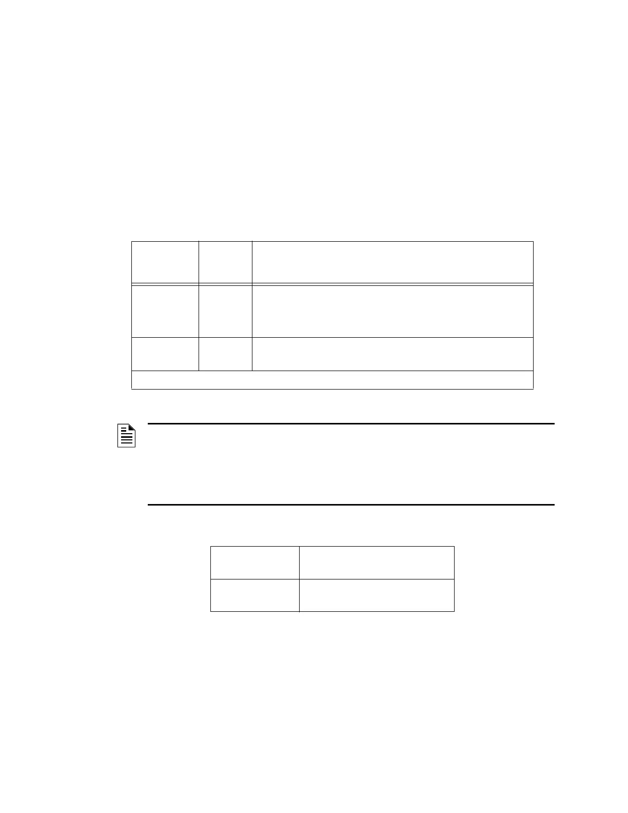
The listed contacts referenced in this section follow the format shown below:
The acronym EMS is used for the term Energy Management System in the wiring diagrams of this section.
Table 5.1 Monitor and Control Module Substitutions
Term
Code
Used in
Manual
Part Number
Control
Module, Relay
Module
CM Control modules:
Relay modules:
FCM-1, XPC, XP5-C, XP6-C, CMX-1, CMX-2
FRM-1, XPR, XP6-R,
CMX-1 relay configuration)
CMX-2 (relay configuration)
Monitor
Module
MM FMM-1, FMM-101, FDM-1, XPM, XP5-M, XP6-MA, XP10-M, MMX-1,
FZM-1
Note: the FDRM-1 acts as both CM or MM, depending on application.
NOTE:
1. The end-of-line resistor used for an FZM-1 or MMX-2 is 3.9K ohms; the end-of-line resistor for an FMM-1,
FMM-101, FDM-1, MMX-1, XP5-M, XP6-C, XP10-M, or MMX-101 is 47K ohms. The XPM uses a 10K ohm
resistor, and the XPC and XP5-C use a 47K ohm resistor.
2. Refer to Section 5.2 “Air Flow Switches” and Section 5.3 “Dedicated Smoke Control System Wiring
Diagrams” of this section for module-specific details that may be relevant to substitutions.
3. Refer to documentation that accompanies modules for specific information on wiring.
1a Form A Contacts
(normally open contacts)
1b Form B Contacts
(normally closed contacts)

 Loading...


