SCS Series Manual — P/N 15712:L 7/18/16 161
HVAC Wiring Diagrams Ratings and Wiring Diagrams
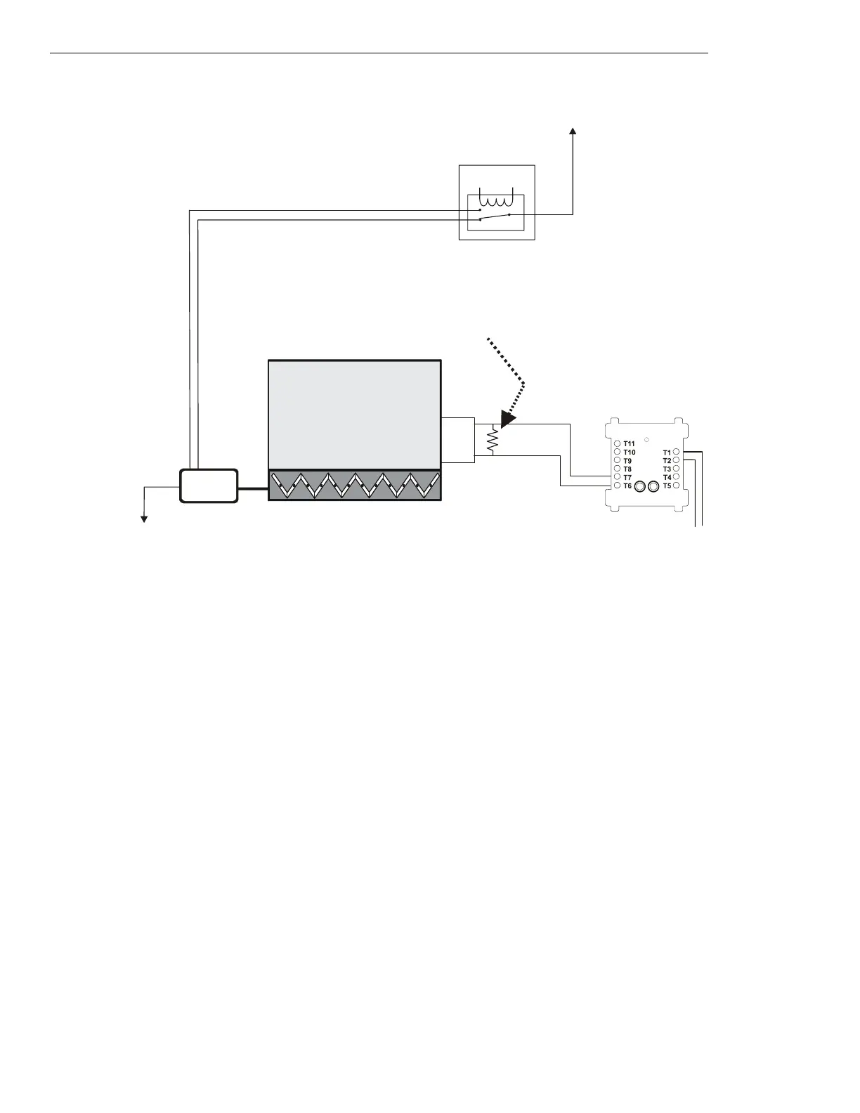
5.5.2 Motorized Dampers
Figure 5.52 Motorized Damper Control - HVAC Switch Group Type 1
Figure 5.52 depicts a motorized damper in an HVAC system with the capability of verification of the
CLOSED state, switch group type 1. In
the above configuration, the EMS is supplying power to the damper closed power line. When power is supplied to the damper closed power
line, the damper closes. When the damper completely closes, the damper closed limit switch is CLOSED, indicating that the damper is in the
CLOSED position. The VER
OFF⁄CL
MM monitors the CLOSED position of the damper closed limit switch. In this case the VER
OFF⁄CL
MM is
activated because the damper is CLOSED.
Power Source
Damper
Open
Power
ELR-47K
(use 3.9K listed ELR with FZM-1)
N/O
COM
Power Return
FMM-1
fan-h14-fs-2.wmf
SLC Loop
VER
OFF/CL
MM
(activated)
Limit Switch
for closed
position
Damper
Closed
Power
AC
MOTOR
DAMPER
CLOSED
Energy
Management
System
*If the SLC device
does not match the
one in this figure, refer
to the SLC manual
appendix, which
contains wiring
conversion charts for
type V and type H
modules.

 Loading...


