48 SCS Series Manual — P/N 15712:L 7/18/16
The SCS⁄SCE SCS-8L⁄SCE-8L Installation
Wiring the Switches
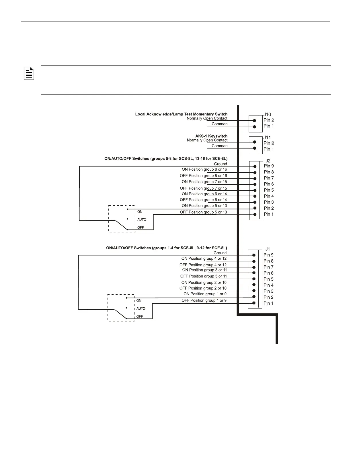
The connectors and pin assignments used to wire switches to the SCS-8L⁄SCE-8L are shown in Figure 3.19. The switches for each switch
group wired to J1 and J2 must be single pull, double throw, center-off type as shown in Figure 3.19. The center-off position is used for Auto-
matic Control. Switches can be obtained from any company which manufactures UL-listed graphic annunciator panels.
Wiring the LEDs or Lamps
The LEDs or Lamps can be powered from 24 VDC or 5 VDC, depending on the load required. Figures 3.21 and 3.22 illustrate connection of
the desired voltage. The following connectors and pin assignments are used to wire LEDs or Lamps to the SCS-8L⁄SCE-8L:
NOTE:
1. The Local Acknowledge/Lamp Test switch wired to J10 must be momentary type.
2. The key-lock switch wired to J11 on the SCS-8L provides access security for all control switches wired to that module. Switches will not
function when the key-lock switch is in its closed position.
J6 +24 VDC LED Power
pin 1 +24 VDC
pin 2 +24 VDC
J8 +5 VDC LED Power
pin 1 +5 VDC
pin 2 +5 VDC
scs8lsw.wmf
Figure 3.19 Switch Wiring for SCS-8L⁄SCE-8L

 Loading...


