40 SCS Series Manual — P/N 15712:L 7/18/16
The SCS⁄SCE Preliminary SCS-8⁄SCE-8 Design Considerations
3.4.7 Dipswitch Setting
The eight dipswitches are used to control the function of the SCS⁄SCE. The dipswitches perform the functions as listed in Table 3.4, where:
switches 1-5 control the combinations of switch group types; switch 6 controls whether the SCS⁄SCE operates in the FSCS or the HVAC
mode; switch 7 selects Dedicated or Non-dedicated System operation when in the FSCS mode or enables/disables the Control-By-Event
lockout when manual operation is initiated in the HVAC mode; and switch 8 installs or removes the end-of-line termination resistor.
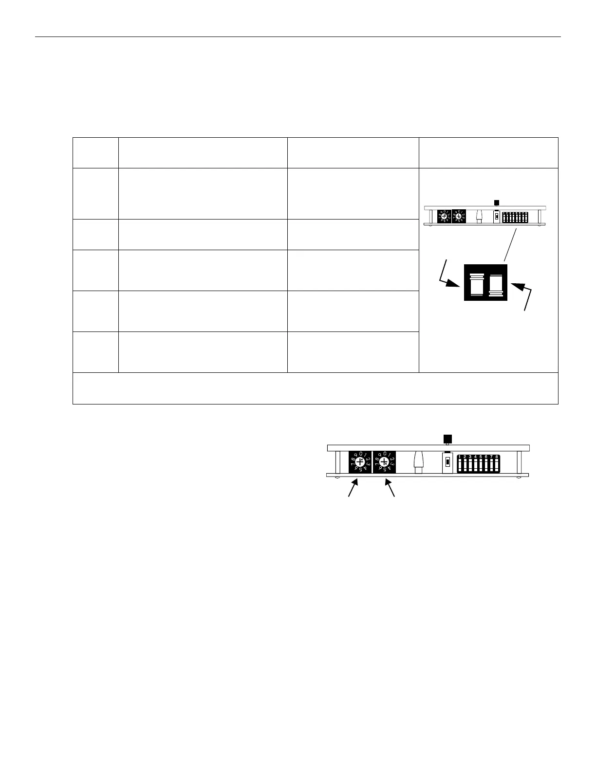
3.4.8 EIA-485 Addressing
The SCS-8 communicates with the FACP on the EIA-485 data line.
Each SCS-8 requires a unique address so that the FACP can properly
route data. There are 32 valid addresses in an FACP EIA-485 circuit
in ACS mode, numbered 1-32, and each address provides the SCS
with 64 points of monitor and control capability. Each SCS-8⁄SCE-8
uses one EIA-485 protocol address and its respective point capacity
(64 points). The first 32 points are used for the SCS-8; the second 32
are used for the SCE-8.
Addressing the SCS-8 is accomplished by using the two rotary deci-
mal switches mounted on the SCS-8. The decimal switches must be
set to any of the available valid addresses (1-32) of the FACP. Each SCS-8 must be set to an address that is different than all other EIA-485
driven devices (annunciators, other SCS-8s, etc.).
The rotary switches are set by using a screwdriver to position the indicating mark on the rotary portion of the switch next to the desired digit.
For example, to set address 14, the 'TENS' switch is set to 1 and the 'ONES' switch is set to 4.
Table 3.4 SCS Dipswitch Mode Configurations
SWITCH
NUMBER
DESCRIPTION FUNCTION SWITCH LOCATION & POSITION
1 to 5 Selects which combination of control/monitor
modules are assigned to each SCS-8⁄SCE-8
toggle switch group
See Table 3.5 on page 55 for
FSCS Mode.
See Table 3.10 on page 67 for
HVAC Mode.
6* Selects FSCS Mode or HVAC Mode for all 16
SCS-8⁄SCE-8 toggle switch groups
ON = FSCS Mode
OFF = HVAC Mode
7* For FSCS Mode, selects Dedicated or Non-
dedicated System for all 16 SCS-8⁄SCE-8
toggle switch groups
ON = Dedicated
OFF = Non-dedicated
For HVAC Mode, enables/disables Control-
By-Event lockout when manual operation is
initiated at the SCS-8⁄SCE-8
ON = Enabled
OFF = Disabled
8 Installs or removes the built-in 120 ohm EIA-
485 end-of-line termination resistor (see
Figure 3.14)
ON = Installed
OFF = Removed
*Must be set “OFF” for INA, or when the SCS module is directly connected to the EIA-485 bus of an NFS-320, NFS2-640, or NFS-640
FACP.
Switch set to
"OFF" position
Switch set to
"ON" position
Switch Locations
Figure 3.4 SCS Address Switches
ONES
TENS
SCS-SWIT.wmf

 Loading...


