SCS Series Manual — P/N 15712:L 7/18/16 47
SCS-8L⁄SCE-8L Installation The SCS⁄SCE
Programming and Testing the Smoke Control Station
This completes the SCS-8⁄SCE-8 installation. After programming the fire alarm control panel to accept the SCS-8⁄SCE-8, fully test the sys-
tem to ensure that each switch performs its intended function, each LED lights as required, and that the SCS-8⁄SCE-8 can perform the func-
tions outlined in Section 3.8.1 “Firefighter's Smoke Control Station (FSCS) Mode” (if operating in FSCS Mode) or Section 3.8.2 “Heating,
Ventilating & Air Conditioning (HVAC) Mode” (if operating in HVAC Mode).
3.7 SCS-8L⁄SCE-8L Installation
Custom Graphic Annunciators
If a designer is using SCS-8L⁄SCE-8L modules for the system design, the modules must be mounted in a graphic annunciator backbox and
interfaced with switches and lamps on the faceplate. Ensure that selected backboxes are UL-listed for the combination according to the UL
category code UUKL. See Appendix C, “Special Applications”, on page 202 for a sample application.
CHS-4L Installation
The SCS-8L⁄SCE-8L modules mount on four standoffs inside of a custom graphic annunciator cabinet. Alternately, the modules can be
installed in a standard CHS-4L low-profile chassis for mouning in a cabinet.
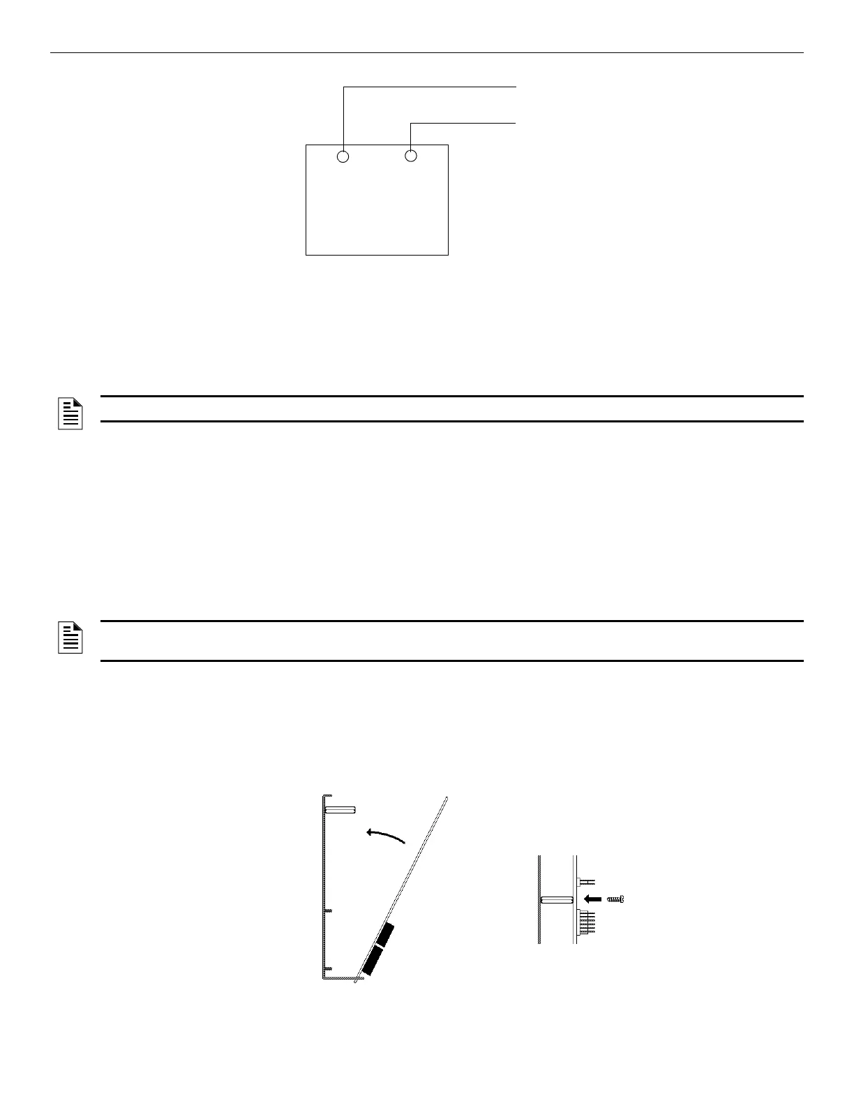
Slip the bottom edge of the SCS-8L into the first slot on the chassis, swing the module towrard the standoffs and secure it to the chassis with
the screws provided, as shown in Figure 3.18. If an SCE-8L is required, plug one end of the annunciator expander ribbon cable into connec-
tor J1 on the SCS-8L. Connect the other end of the annunciator expander ribbon cable to connector J1 on the SCE-8L. Slip the bottom edge
of the SCE-8L into the second slot on the chassis and swing the module toward the standoffs and secure it to the chassis with the screws pro-
vided. Repeat this procedure for the second set of SCS-8L⁄SCE-8L modules to be installed in positions 3 and 4 on the chassis. Connect the
wiring as shown in Figure 3.19, Figure 3.20, Figure 3.21, and Figure 3.22.
Regulated power-limiting
power supply listed for fire
protective signaling.
(+) 24 VDC
Power
(–) 24 VDC
Common
(+) 24 VDC Power
to SCS-8 TB1-3
(–) Common
to SCS-8 TB1-5
Figure 3.17 Power Supply Connections
NOTE: Refer to the “Restrictions” section of this manual for information on compatible software part numbers.
NOTE: The SCS-8L⁄SCE-8L can only be mounted in the CHS-4L chassis for the HVAC mode. If using the FSCS mode the SCS-8L⁄SCE-
8L must be installed in a custom graphic annunciator backbox.
c
Figure 3.18 Installing SCS-8L⁄SCE-8L Modules

 Loading...


