50 SCS Series Manual — P/N 15712:L 7/18/16
The SCS⁄SCE SCS-8L⁄SCE-8L Installation
Installing Relay Modules
An optional Relay Expander Module (LDM-R32) may be used in place of wiring LEDs to the SCS-8L.
Secure the LDM-R32 to the SCS-8L with the standoffs provided (see Figure 3.23). Attach ribbon cables between the LDM-R32 and the
SCS-8L for each group of relays needed (connectors J5, J6, and J7 on the LDM-R32 to J3, J4, and J5 on the SCS-8L respectively) as illus-
trated in Figure 3.24.
Connect the Relay Power Ribbon Cable between J10 on the LDM-R32 and J7 on the SCS-8L. This connection supplies the power needed to
energize the LDM-R32's relay coils during activation. For more information on the LDM-R32, refer to The LDM Series Lamp Driver
Annunciator Modules, document number 15885.
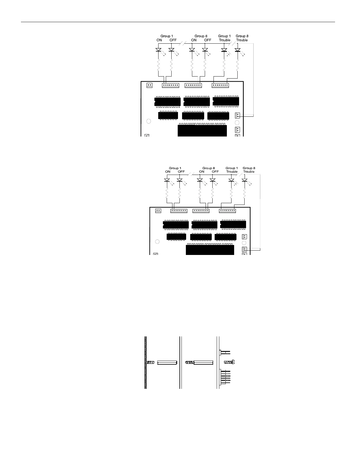
LEDs:
Use green for ON,
yellow for OFF, amber
for Trouble, green for
All AUTO and amber
for MANUAL
Use 680 ohm, 1/4-watt
resistors for each
point
Figure 3.21 LED Connection @ 5 VDC (Using High Efficiency 2mA LEDs)
LEDs:
Use green for ON,
yellow for OFF, amber for
Trouble, green for All
AUTO and amber for
MANUAL
Use 10K ohm, 1/4-watt
resistors for each point
Figure 3.22 LED Connection @ 24 VDC (Using High Efficiency 2mA LEDs)
Standoff Standoff
Chassis SCS-8L LDM-R32
Figure 3.23 Installing Optional Relay Modules

 Loading...


