EasyManua.ls Logo

HP 1650B User Manual

HP 1650B
346 pages
To Next Page IconTo Next Page
To Previous Page IconTo Previous Page
Page #33 background imageLoading...
Page #33 background image
Definite-Length Block
Definite-length block response data allows any type of device-dependent
Response Data
data to be transmitted over the system interface as a series of g-bit binary
data bytes. This is particularly useful for sending large quantities of data
or g-bit extended ASCII codes. The syntax is a pound sign ( # ) followed
by a non-zero digit representing the number of digits in the decimal
integer. After the non-zero digit is the decimal integer that states the
number of g-bit data bytes being sent. This is followed by the actual data.
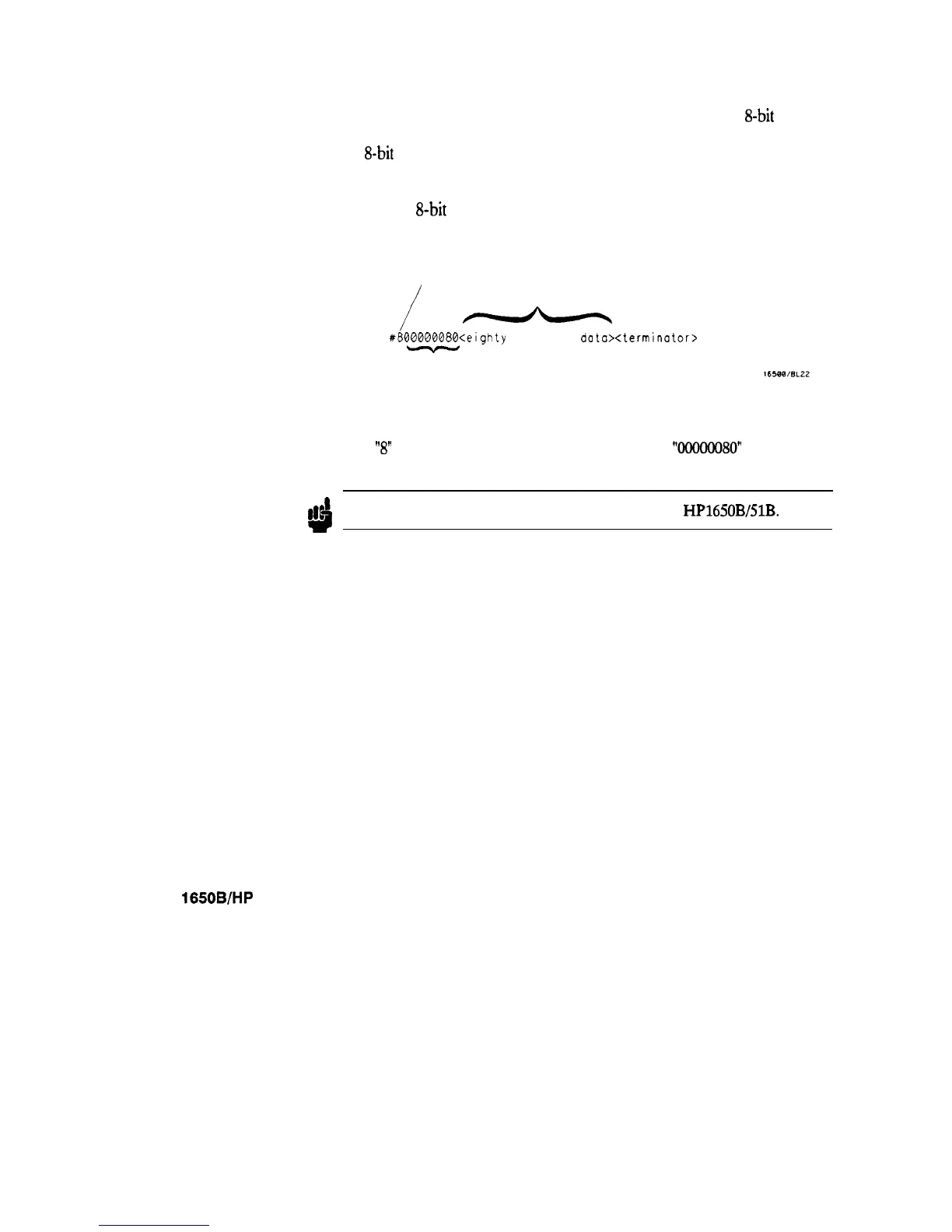
For example, for transmitting 80 bytes of data, the syntax would be:
NUMBER OF DIGITS
THAT FOLLOW
ACTUAL DATA
/
-
#800000080<elghty
bytes of
data><terminator>
NUMBER OF BYTES
TO BE TRANSMITTED
Figure 1-3. Definite-length Block Response Data
The
“8”
states the number of digits that follow, and
‘WOOOO80”
states the
number of bytes to be transmitted.
Note
!!b
Indefinite-length block data is not supported on the HP1650B/51B.
HP 1650B/HP 16518
Programming Reference
introduction to Programming an Instrument
1-17

Table of Contents

Question and Answer IconNeed help?

Do you have a question about the HP 1650B and is the answer not in the manual?

HP 1650B Specifications

General IconGeneral
CategoryLogic Analyzer
Model1650B
Number of Channels80
Maximum Clock Rate100 MHz
Glitch TriggerYes
Transitional TimingYes
DisplayCRT

Summary

Chapter 1 Introduction to Programming an Instrument

Programming Syntax and Concepts

Explains command format, structure, headers, parameters, and syntax rules for instrument control.

Instrument Programming Basics

Covers initialization, example programs, data retrieval, and response formats.

Chapter 2 Programming Over HP-IB

Chapter 3 Programming Over RS-232C

Chapter 5 Common Commands

Key Common Commands

Details essential commands like *CLS, *ESE, *IDN, *RST for status and identification.

Chapter 6 System Commands

Key System Commands

Details core commands like ARM, DATA, LOCKout, LONGform, STARt, STOP.

Chapter 7 MMEMory Subsystem

File Management Commands

Covers AUToload, CATALOG, COPY, DOWNLOAD, LOAD, PACK, PURGE, RENAME, STORE, UPLOAD.

Chapter 10 MACHine Subsystem

Machine Configuration Commands

Covers commands like NAME, TYPE, ARM, ASSign for machine setup.

Chapter 11 SFORmat Subsystem

State Format Configuration

Details SFORmat selector and commands like CLOCK, CPERiod, LABel.

Chapter 12 STRace Subsystem

State Trace Qualification

Details BRANch, FIND, PREStore, RESTart for trace sequence control.

Chapter 13 SLISt Subsystem

State Listing Configuration

Details commands like COLumn, DATA, LINE, MMODE, PATtern for listing setup.

Chapter 14 SWAVeform Subsystem

Waveform Display Configuration

Details ACCumulate, DELay, INSert, RANGe, REMove for waveform display setup.

Chapter 16 COMPare Subsystem

Compare Data Configuration

Details CMASk, COPY, DATA, FIND, RANGe, RUNTil for comparison setup.

Chapter 17 TFORmat Subsystem

Timing Format Configuration

Details LABel, REMove, THReshold for timing format setup.

Chapter 18 TTRace Subsystem

Timing Trace Configuration

Details AMODe, DURation, EDGE, GLITch, PATTern for timing trace setup.

Chapter 19 TWAVeform Subsystem

Timing Waveform Configuration

Details ACCumulate, DELay, INSert, MMODe, OCONdition for waveform setup.

Related product manuals