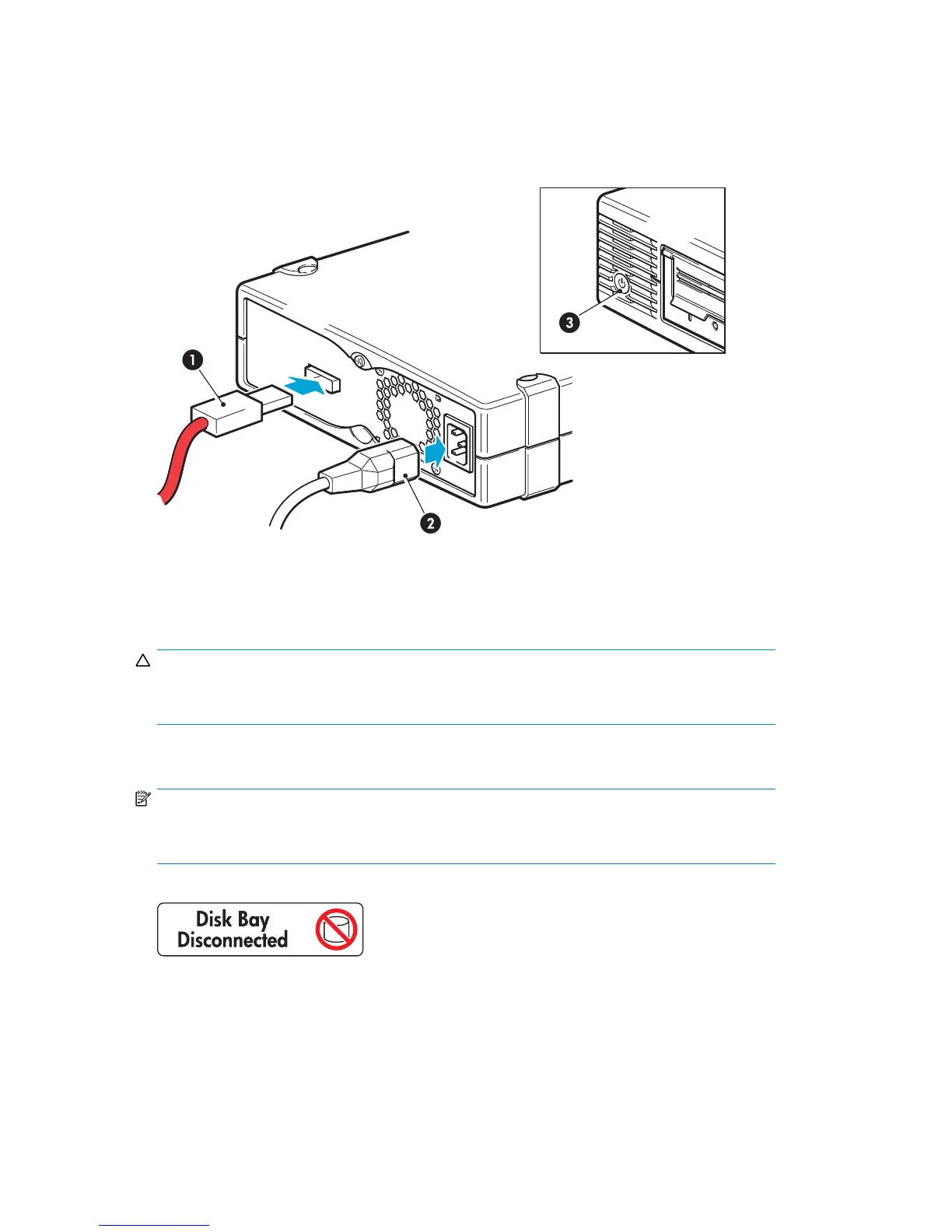
8. Connect the other end of the SAS cab le (threaded through the blanking plate to the outside of the
server) to the connector on the rear of the tape drive.
9. Plug the power cord securely into the socket on the rear panel of the drive and plug the other
end of the power cord into the power outlet. The power on/off switch is on the front panel, see
Figure 26 on page 46.
1. SAS connector
3. P ower on/off switch
2. Power c
onnector
Figure 26 Connecting the cables to the tape drive
CAUTION:
Never use a cable where power is supplied through the SAS connector because this may
damage t
he drive. For external drives, always use the supplied power cord.
10. Ifyouhavelosttheuseofadiskbay(seeStep 2 on page 42), we strongly recommend that you
attach the s upplied sticker to the blanking plate of the disk bay to show that it is disconnected.
NOTE:
If you subsequently install a hard d isk in this bay, it will not work. This does not mean there
is a fault with either the disk or the server.
Figure 27 Sticker for highest-numbered hard disk bay
11.
Now go to “Reboot the server” on page 46.
Reboot the server
Switch o n the tape drive (the power on/off switch is on the front panel) and power up the server.
46
Installing an external Ultrium tape drive by connecting to an internal SAS por t
 Loading...