Cluster management configuration example
Network requirements
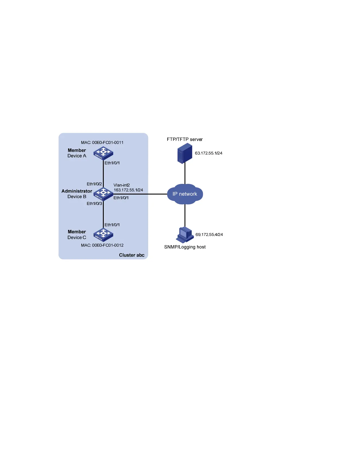
• Three switches form cluster abc, whose management VLAN is VLAN 10. In the cluster, Switch B
serves as the management switch (Administrator), whose network management interface is
VLAN-interface 2; Switch A and Switch C are the member switches (Member).
• All the devices in the cluster use the same FTP server and TFTP server on host 63.172.55.1/24, and
use the same SNMP NMS and log services on host IP address: 69.172.55.4/24.
• Add the device whose MAC address is 000f-e201-0013 to the blacklist.
Figure 44 Network diagram for cluster management configuration
Configuration procedure
1. Configure the member switch Switch A
# Enable NDP globally and for port Ethernet 1/0/1.
<SwitchA> system-view
[SwitchA] ndp enable
[SwitchA] interface Ethernet 1/0/1
[SwitchA-Ethernet1/0/1] ndp enable
[SwitchA-Ethernet1/0/1] quit
# Enable NTDP globally and for port Ethernet 1/0/1.
[SwitchA] ntdp enable
[SwitchA] interface Ethernet 1/0/1
[SwitchA-Ethernet1/0/1] ntdp enable
[SwitchA-Ethernet1/0/1] quit
# Enable the cluster function.
[SwitchA] cluster enable
2. Configure the member switch Switch C
As the configurations for the member switches are the same, the configuration procedure for Switch C is
123