164
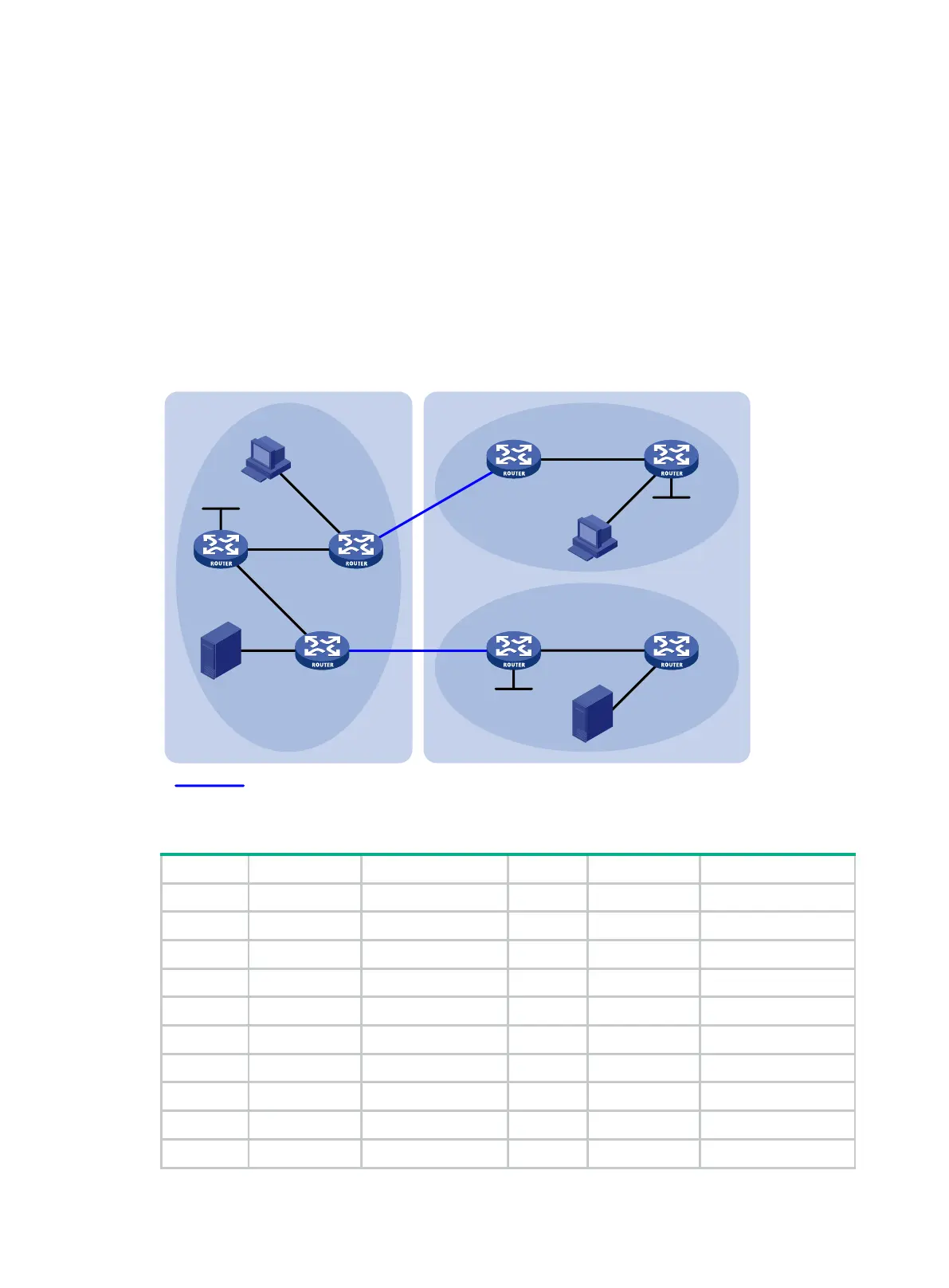
The network has two ASs: AS 100 and AS 200. OSPF runs within each AS. BGP runs between
the two ASs.
PIM-SM 1 belongs to AS 100, and PIM-SM 2 and PIM-SM 3 belong to AS 200. Each PIM-SM
domain has a minimum of one multicast source or receiver.
To meet the network requirements, perform the following tasks:
Configure Loopback 0 as the C-BSR and C-RP of the related PIM-SM domain on Router A,
Router D and Router G.
According to the peer-RPF forwarding rule, the routers accept SA messages that pass the
filtering policy from its static RPF peers. To share multicast source information among PIM-SM
domains without changing the unicast topology structure, configure MSDP peering
relationships for the RPs of the PIM-SM domains and configure the static RPF peering
relationships.
Figure 54 Network diagram
Table 14 Interface and IP address assignment
Source 1 — 192.168.1.100/24 Router D GE1/0/1 10.110.5.1/24
Source 2 — 192.168.3.100/24 Router D GE1/0/2 10.110.3.2/24
Router A GE1/0/1 10.110.1.1/24 Router D Loop0 2.2.2.2/32
Router A GE1/0/2 10.110.2.1/24 Router E GE1/0/1 10.110.5.2/24
Router A Loop0 1.1.1.1/32 Router E GE1/0/2 192.168.3.1/24
Router B GE1/0/1 10.110.1.2/24 Router F GE1/0/1 10.110.6.1/24
Router B GE1/0/2 192.168.1.1/24 Router F GE1/0/2 10.110.4.2/24
Router B GE1/0/3 10.110.3.1/24 Router G GE1/0/1 10.110.6.2/24
Router C GE1/0/1 10.110.2.2/24 Router G GE1/0/2 192.168.4.1/24
Router C GE1/0/2 192.168.2.1/24 Router G Loop0 3.3.3.3/32
GE1/0/3
GE1/0/2
Router B
Router A
Source 1
AS 100
PIM-SM 1
PIM-SM 3
PIM-SM 2
Loop0
Router D Router E
Router F
Router G
Source 2
GE1/0/2
GE1/0/1
GE1/0/2 GE1/0/1
GE1/0/1
Loop0
Receiver
Receiver
Loop0
BGP peers
GE1/0/1
GE1/0/1
GE1/0/1
GE1/0/2
GE1/0/2
AS 200
GE1/0/3
GE1/0/1
GE1/0/2
GE1/0/2
Router C
 Loading...