5.
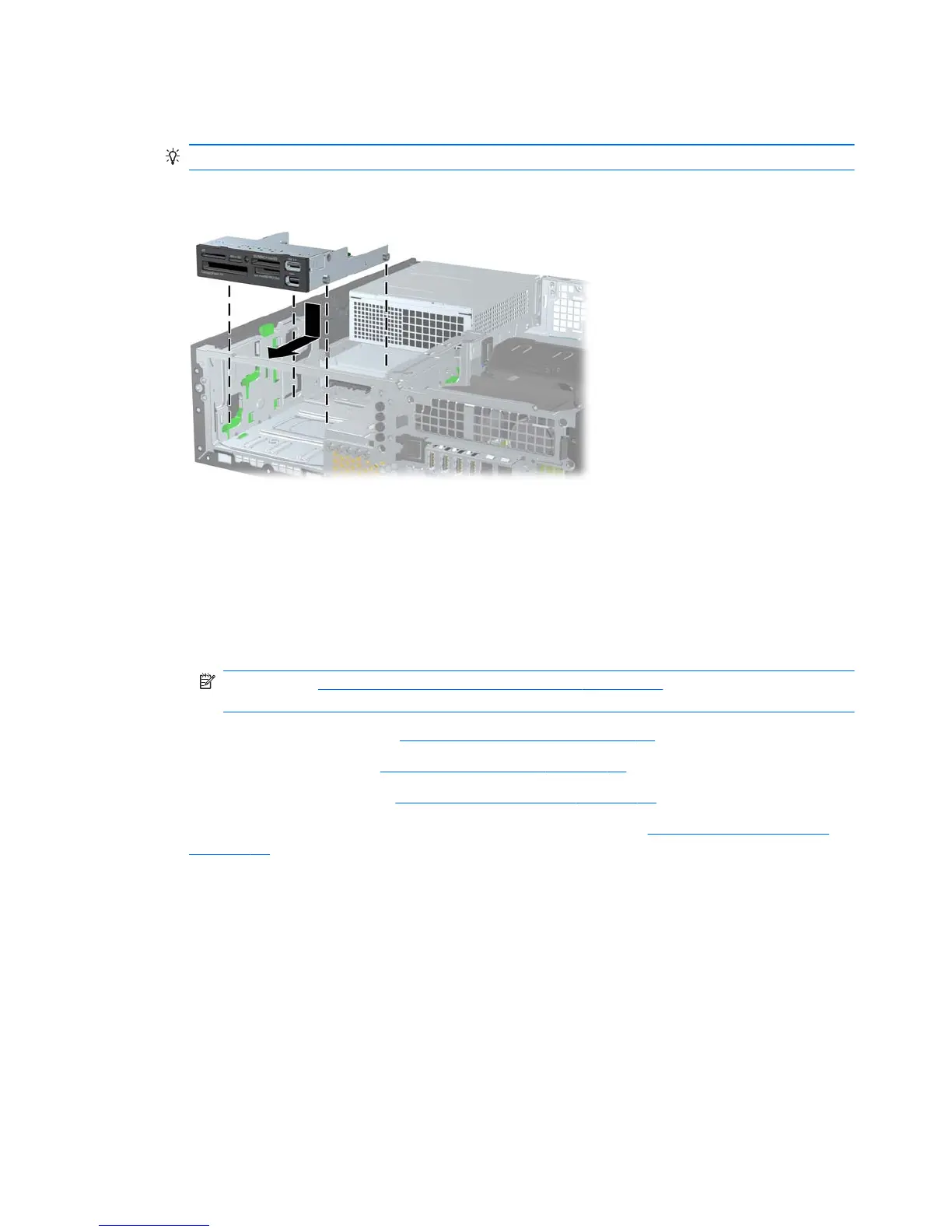
Place the drive's guide screws into the J-slots in the drive bay. Then slide the drive toward the front
of the computer until it locks into place.
TIP: Angle the drive toward one side of the chassis to line up the guide screws with the slots.
Figure 5-23 Installing a drive into the drive cage (media card reader shown)
6.
Connect the drive cables:
a.
If installing a second hard drive, connect the power and data cables to the rear of the drive
and connect the other end of the data cable to the next available (unpopulated) SATA
connector on the system board by following the numbered sequence of the connectors.
b.
If installing a media card reader, connect the USB cable from the media card reader to the
USB connector on the system board labeled MEDIA. If the media card reader includes a
1394 port, connect the 1394 cable to the 1394 PCI card.
NOTE: See Locate system board drive connections on page 80 for an illustration of the
system board drive connectors.
7.
Replace the optical drive. (See
Installing an optical drive on page 85.)
8.
Replace the front bezel (see
Installing the front bezel on page 74).
9.
Replace the access panel (see
Installing the access panel on page 72).
10.
Restore all connections and equipment that you removed during the
Predisassembly procedures
on page 69.
Removing a DX115 Dataport hard drive
To remove a DX115 Dataport hard drive:
1.
If a drive case is installed in the carrier, remove it:
90 Chapter 5 Replacing components ENWW
 Loading...