ASSEMBLY
Assembling the cutting
equipment
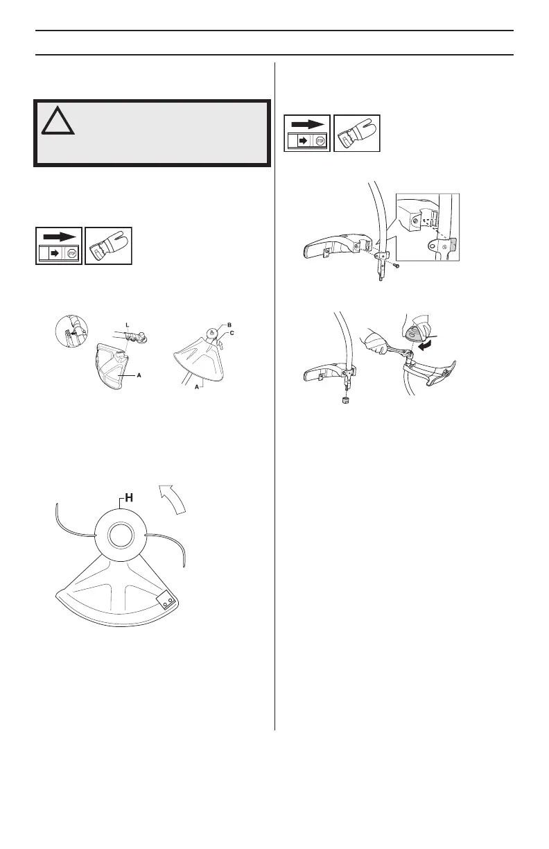
Fitting the trimmer guar
d and
trimmer head
(129L, 129LK)
• Fit the correct tr
immer guard (A) f
or use with the
tr
immer head.
Hook the trimmer guard/combination
guard onto the fitting on the shaft and secure with the
bolt (L).
• Fit the drive disc (B) on the output shaft.
• Turn the output shaft until one of the holes in the drive
disc aligns with the corresponding hole in the gear
housing.
• Insert the locking pin (C) in the hole to lock the shaft.
• Screw on the trimmer head/plastic blades (H) in the
opposite direction to the direction of rotation.
• To dismantle, follow the instructions in the reverse
order.
Fitting the trimmer guard and
trimmer head
(129C)
• Fit the guard as shown in the diagram. Tighten
securely.
• Fit the dust cup on the shaft. The nut must be
completely covered by the dust cup.
• Hold the dust cup with a spanner to prevent the shaft
from rotating.
• Screw the trimmer head onto the shaft.
!
WARNING! Never use a cutting
attachment without an approved guard.
See the chapter on Technical data. If an
incorrect or faulty guard is fitted this can
cause serious personal injury.
 Loading...