Note: Read voltages with a digital multimeter (DVM) capable of storing minimum and maximum readings.
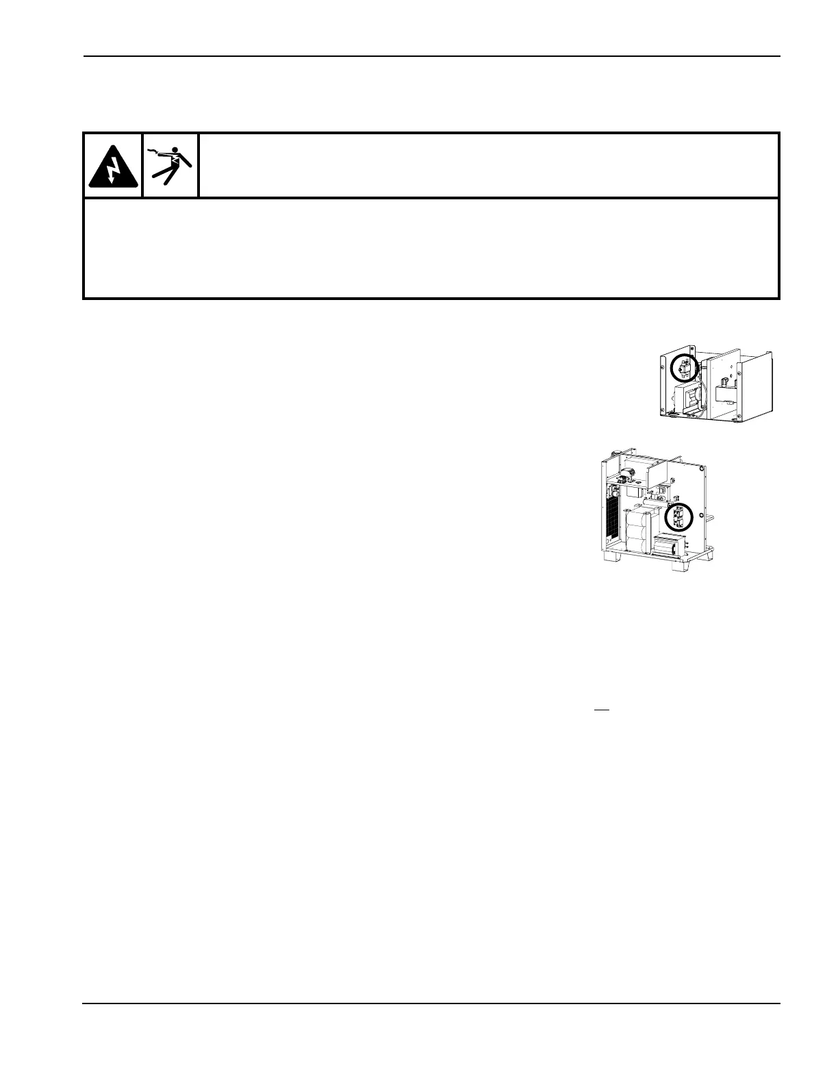
1. Turn OFF all power to the system. Disconnect the 2 terminals (Wire colors red and
red/black) on the line filter (FLTR1) in the ignition console. This will disable the high-
voltage transformer (T1).
2. Remove large fuse F3 (left side of power supply). Check to see if fuse is open.
Note: The 150A fuse is connected to the positive lead. Disconnecting the
fuse does not prevent DC voltage from being present at the
electrode
3. Place the positive lead of the DVM to the (+) side of the input rectifier and the negative lead to the (-) side of the
input rectifier. See the figure on next page. Note that actual connection points are hidden by the capacitor
support bracket in figure.
4. Turn ON power to the system, and start up the system. After the START command has been given, measure
voltage. The input to the chopper at the points described in step 3 should be about +311 VDC. If the input is OK
and the corresponding fuse (F3) is blown, replace the chopper module. If there is no +311 VDC input, verify the
3-phase AC input to the chopper. Also, verify the main contactor (CON1) contacts, connections and associated
wiring. Repair or replace any defective components. To check AC voltage to chopper, perform the same test
again with the DVM in AC mode. Check voltage between A - B, B - C and A - C. The voltage should be 220 VAC.
5. If voltage from step 4 is +311 VDC and the fuse (F3) is not blown, check the output of the chopper(s).
CH1: • Place the positive lead of the DVM at point (+) WORK on the chopper module (wire #39)and negative
lead at point (-) TORCH (wire #38). See the figure on the next page.
• Turn ON the system and give the START command. After the START command has been given
measure the voltage. If the output from these points is greater than 311 VDC, the chopper may be
OK. If the voltage is lower than 311 VDC, replace the chopper.
• If the voltage is 311 VDC, re-install the fuse (F3) and measure the voltage as above. A low voltage
reading with this method means either an external short or faulty chopper.
• Verify that the error code number is 020 (no pilot arc sensed) and replace chopper.
MAINTENANCE
HPR130 Manual Gas Instruction Manual 5-31
3
Chopper module test procedure
WARNING
SHOCK HAZARD: Use extreme care when working near the chopper modules. The large electrolytic
capacitor(s) (blue-cased cylinder(s) store large amounts of energy in the form of electric voltage.
Even if the power is off, dangerous voltages exist at the capacitor terminals, on the chopper, and the
diode heatsinks. Never discharge any capacitor with a screwdriver or other implement … explosion,
property damage and/or personal injury will result.
 Loading...


