INSTALLATION
HPR130 Manual Gas Instruction Manual 3-33
5
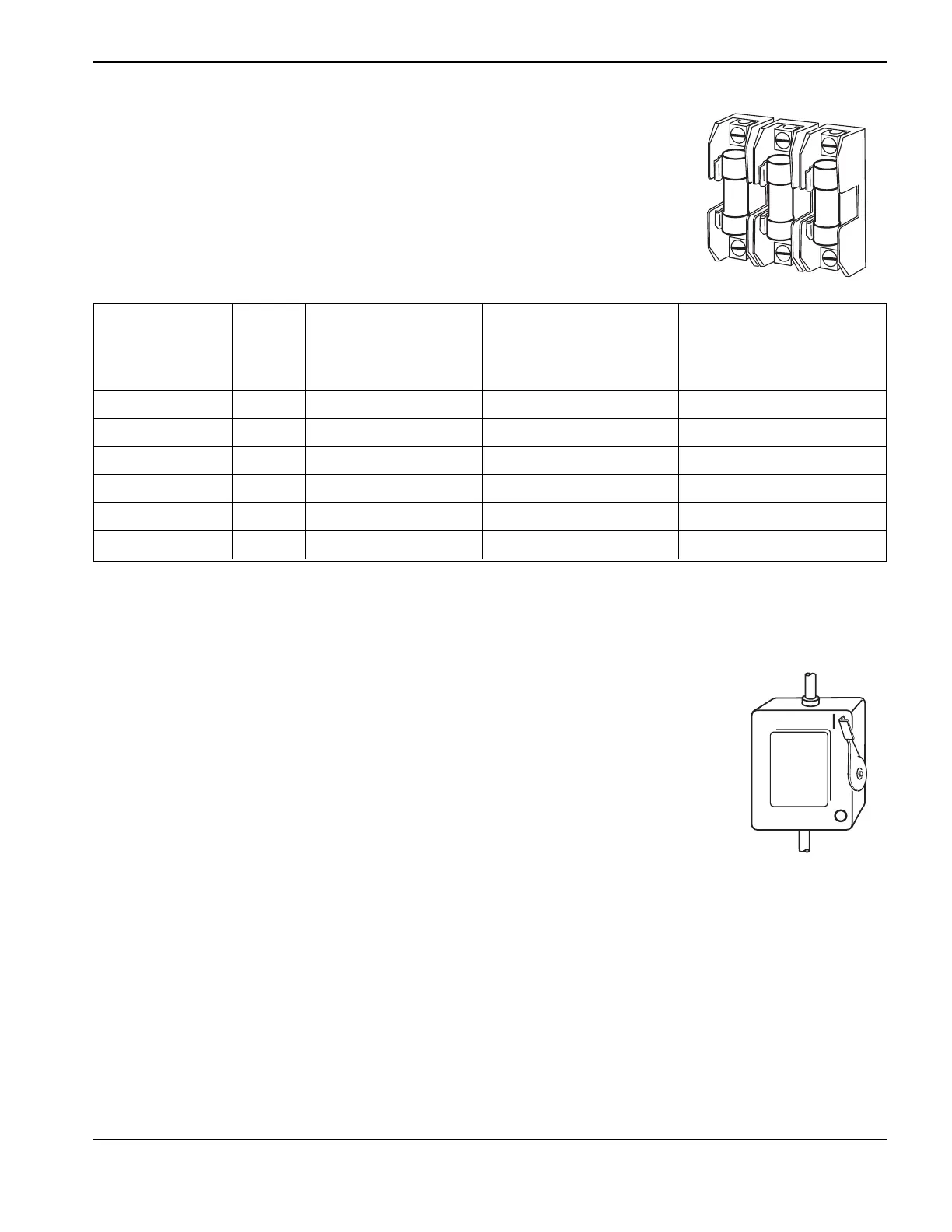
Line disconnect switch
The line disconnect switch serves as the supply-voltage disconnecting (isolating) device.
Install this switch near the power supply for easy access by the operator.
Installation must be performed by a licensed electrician and according to applicable national
or local codes.
The switch should:
• isolate the electrical equipment and disconnect all live conductors from the supply
voltage when in the “OFF” position
• have one “OFF” and one “ON” position clearly marked with “O” (OFF) and “l” (ON)
• have an external operating handle capable of being locked in the “OFF” position
• contain a power operated mechanism that serves as an emergency stop
• have slow-blow fuses installed for the proper breaking capacity (see table above).
Power requirements
General
All switches, slow-blow fuses and power cables are customer supplied and must be
chosen as outlined by applicable national or local electrical codes. Installation must
be performed by a licensed electrician. Use a separate primary line disconnect
switch for the power supply.
Power cable
Wire sizes vary based on the distance of the receptacle from the main box. The wire sizes listed in the table above
were taken from the National Electric Code 1990 handbook, table 310.16 (USA). Use a 4-conductor Type SO input
power cable with a conductor temperature rating of 60° C (140° F). Installation must be performed by a licensed
electrician.
Note: Cable AWG recommendations taken from table 310-16 of the National Electric
Code handbook (USA).
Recommended Cable size
for 15 m (50 feet)
Input Rated input current Recommended maximum length
voltage Phase @ 19.5 kW output slow-blow fuse size Rated for 60° C
200/208 VAC 3 62/58 amps 85 amps 30 mm
2
(3 AWG)
240 VAC 3 52 amps 65 amps 26 mm
2
(4 AWG)
400 VAC 3 32 amps 40 amps 10 mm
2
(8 AWG)
440 VAC 3 28 amps 35 amps 8 mm
2
(8 AWG)
480 VAC 3 26 amps 35 amps 8 mm
2
(8 AWG)
600 VAC 3 21 amps 30 amps 6 mm
2
(10 AWG)
 Loading...


