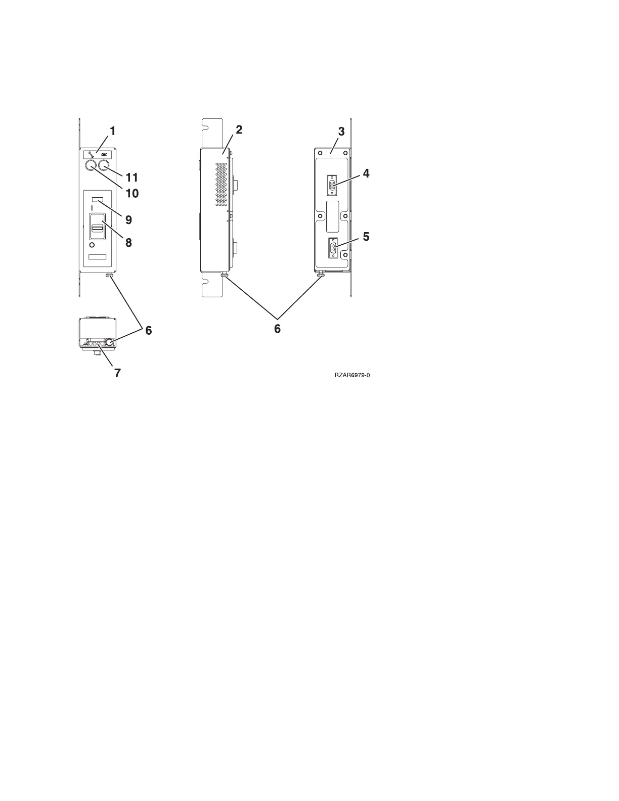
2. Press the (green) Start Service button (number 10 in figure 1) on the UEPO assembly.
3. Switch the UEPO bypass switches on both BPCs to the Bypass position (to the right).
Figure 1. UEPO card assembly
4. Ensure that the red switch (number 8 in figure 1) on the front of the EPO panel is in the ON position.
5. Loosen, but do not remove, the two 8mm M5 mounting screws. Slide the assembly forward and away
from the frame.
6. Verify that all cables (numbers 4, 5, and 7 in figure 1) are labeled for plug location and then unplug the
cables from the UEPO card assembly.
To replace the Unit Emergency Power Off (UEPO) card assembly:
1. Plug all cables (numbers 4 and 5 in figure 1) to the UEPO card assembly, ensuring that the plug
location and the cable label agree.
2. Place the assembly over the two 8mm M5 screws, then, slide it back and tighten the screws.
3. Install the external cable, if required, to connector J2 (number 7 in figure 1).
v If the external EPO connection is installed, the internal toggle switch (number 6 in figure 1) is
mechanically forced into the ROOM EPO ACTV position (to the right).
v If there is no external EPO cable, manually set the internal toggle switch (number 6 in figure 1) to
the ROOM EPO BYPASS position (by pulling the knob to the left).
4.
Ensure that the red UEPO switch (number 8 in figure 1) on the front of the UEPO panel is on (up
position).
5. Switch the UEPO BYPASS switches on both BPC’s back to NORMAL mode.
6. Press the (white) Service Complete button (number 11 in figure 1) on the UEPO switch to indicate
completion of this procedure.
This ends the procedure.
Models 870 and 890 - VPD card
For use by authorized service providers.
Use this procedure to remove or replace a VPD card on the Models 870 and 890.
134 Hardware (Remove and Replace; Part Locations and Listings)
 Loading...


