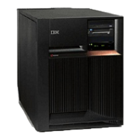
The Models 270, 800, and 810 may be housed in an FC 0551 frame. The upper and lower system units
are placed on rails in the frame. If you are working on the upper or lower unit in a 0551 frame, follow
these instructions and access the internal parts by opening the front cover and sliding the system unit out
on its rails.
Attention: The control panel is sensitive to electrostatic discharge. See Work with electrostatic
discharge-sensitive parts.
To remove or replace the control panel (NB1):
1. Power off the system. See Power on/off the system and logical partitions.
2. Disconnect the ac power cord from the system unit. On a Model 270, 800, or 810 with a system unit
expansion attached, disconnect both the system line cord and the expansion unit line cord.
3. Open the front cover. See Models 270, 800, and 810 - Covers.
4. Pull on the two side fasteners to release the control panel assembly.
5. Slide the panel partially out of the frame.
6. Remove the control panel cover.
7. Are you here to exchange the processor capacity and interactive cards?
v Yes: Perform the following:
a. Pull the processor capacity or interactive cards off the control panel card and put the new ones
in their place. Note the position and orientation of each card. See Control panel - Models 270,
800, and 810.
b. Reinstall the control panel card by reversing the procedure to this point.
c. Go to Verify the repair.
This
ends the procedure.
v No: Disconnect the cables that are attached to the backside of the control panel.
8. Remove the control panel from the frame.
9. Remove the processor capacity and interactive cards. Note the position and orientation of each card.
10. Install the processor capacity and interactive cards into the new panel and replace the cover.
11. Remove the plastic tab on the front of the control panel that has the machine type and serial number.
The tab should then be installed onto the new control panel.
12. Reverse the above procedure to install the panel.
13. After exchanging an item, go to Verify the repair.
This
ends the procedure.
Models 270, 800, and 810 - Covers
For use by authorized service providers.
Use this procedure to remove or replace covers on the Models 270, 800, and 810.
Attention: If removing the cover while powered on, errors may occur due to Electromagnetic Interference.
To remove the front cover: Pull the top of the cover away from the frame.
To remove the back cover: Lift the cover up to remove it.
To remove the right side cover:
1. Remove the thumbscrews that fasten the cover to the back of the system frame.
2. Push the cover toward the back of the system to remove it.
To remove the left side cover:
1. Remove the screws that fasten the cover to the back of the system frame.
Analyze hardware problems 7
 Loading...


