v The right column is used to determine the IOP to which an IOA is assigned.
v The first position in the list must be an IOP. The remaining positions may be IOPs or IOAs. IOAs are
assigned to the first IOP located to their left in the list. Although IOAs can be manually reassigned
using SST/DST, the IOA assignments return to the default order after each IPL.
Table 2. Identify the IOP to which IOAs are assigned
Multi-adapter bridge domain / PCI bridge set IOA assignment rules
C01 - C04 C01, C02, C03, C04
C05 - C09 C05, C06, C07, C08, C09
C11 - C15 C11, C12, C13, C14, C15
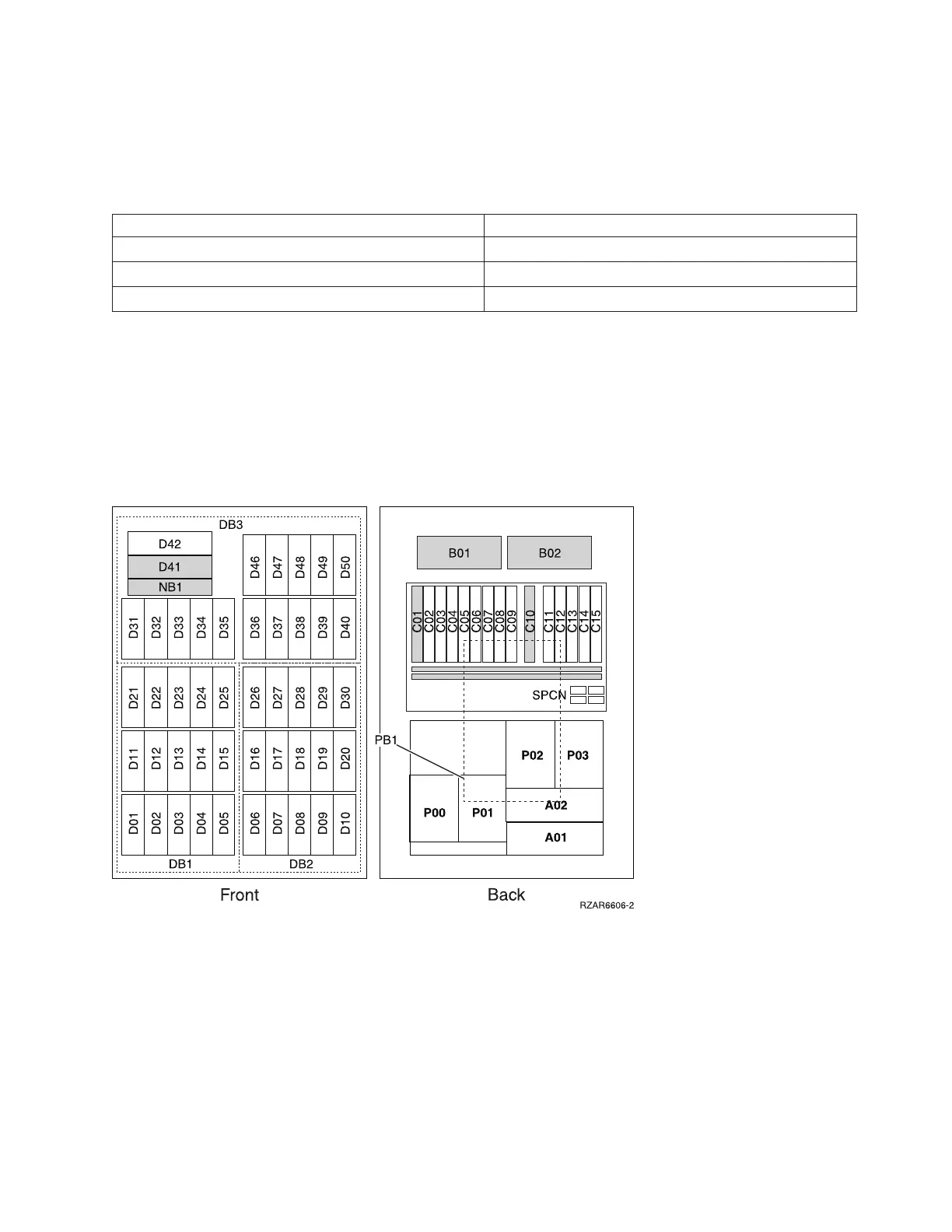
Locations — FC 5094 Expansion I/O Tower
For use by authorized service providers.
The following diagram shows FRU layout in the FC 5094 Expansion I/O Tower. Use it with the tables
below. If you need address information, refer to Addresses — FC 5094 Expansion I/O Tower.
Figure 1. FC 5094 Expansion I/O Tower
Note: Do not install power supplies P00 and P01 AC jumper cables on the same AC module.
The following table gives the components available for callout on the FC 5094, FC 5294, and FC 8094
expansion I/O units. It matches those components with the FRU containing the the component. The other
columns give location information, CCIN information, a link to a remove and replace procedure, and
additional comments.
Table 1. FRU locations and failing components for FC 5094 Expansion I/O Tower
Analyze hardware problems 309
 Loading...


