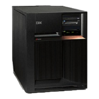
FC 5094, FC 5294 - Cards (dedicated)
FC 8094-001 (lower half), FC 9094 - Cards (concurrent)
FC 8094-001 (lower half), FC 9094 - Cards (dedicated)
FC 9094 - Control panel - NB1
FC 5074, FC 5079, FC 5094, FC 5294, FC 9079, FC 9094 - Covers
FC 5094, FC 9094 - Device board - DB1 and DB2
FC 5094, FC 9094 - Device board - DB3
FC 5094, FC 9094 - Disk unit (concurrent)
FC 5094, FC 9094 - Disk unit (dedicated)
FC 5094 - Display panel - NB1
FC 5094, FC 9094 - Power distribution backplane - PB1
FC 5094, FC 9094 - Power supply - P00, P01, P02, and P03
FC 5094, FC 9094 - Removable media - D41 and D42
FC 9094 - Time of day (TOD) battery
FC 5094, FC 9094 - Tower card - CB1
FC 5094, FC 9094 (with single line cord) - AC module - A01 and A02
For use by authorized service providers.
Use this procedure to remove or replace the AC module - A01 and A02 in an FC 5094, FC 9094 (with
single line cord).
To remove or replace the AC module - A01, A02:
1. Is the system or expansion unit with the failing AC module powered on?
v Yes: Continue with the next step.
v No: Go to step 3 (See page 171).
2.
Is the failing AC module location (2) A02? See Locations and addresses for system or expansion unit
you are working on.
v No: The failing AC module is location (1) A01. Power off the system and continue with the next step.
v Yes: Do not power down the system or expansion unit if it is powered on; this procedure can be
performed concurrently. Continue with the next step.
3. Open the rear cover. See FC 5074, FC 5079, FC 5094, FC 5294, FC 9079, FC 9094 - Covers.
4. Trace and disconnect the ac input line cord that connects to the AC module that needs replacing. See
Locations and addresses for the expansion unit you are working on.
Attention: Do not disconnect the other non-failing unit ac line cord when powered on.
5. Disconnect the power supply jumper cords from the AC module that you are working on.
Attention: Do not disconnect the other system AC module power supply jumper cords.
6. Remove the top and bottom screws that hold the AC module to the expansion unit.
7. Remove the AC module unit.
Analyze hardware problems 171
 Loading...


