v Yes: After exchanging an item, go to Verify the repair.
This ends the install procedure.
8.
There is a power problem. One of the following is the problem:
v The new unit is defective.
v The backplane was damaged during the device concurrent maintenance procedure.
v There is a new problem with the power subsystem.
This ends the procedure.
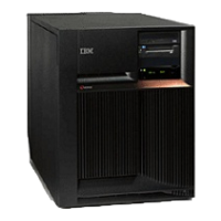
Model 825 - System unit backplane - CB1 and Power bus bar assembly
For use by authorized service providers.
Use this procedure to remove or replace the system unit backplane - CB1 or the Power bus bar assembly
on a Model 825.
To remove or replace the system unit backplane (CB1) and the Power bus bar assembly (if necessary):
1. Power off the system. See Power on/off the system and logical partitions.
2. Unplug the power cord from the back of the system unit. On a Model 825 with dual line cords,
disconnect both of the system line cords.
3. Remove the left side, right side, and top cover. See Model 825 - Covers.
4. Remove the PCI cards and processor cards (C13, M01, and M02), and the HSL card at MB1. See
Locations - Model 825 for the correct remove and replace procedure links. Note the locations to aid in
replacing them correctly.
5. Remove the white plastic shield that is covering the SCSI and air moving devices (AMDs), located on
the left side of the system.
Figure 1. The white shield covering the SCSI and air moving devices
Analyze hardware problems 45
 Loading...


