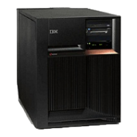
Use this procedure to remove or replace the air moving device (AMD) - B03 in the Models 270, 800, and
810.
The Models 270, 800, and 810 may be housed in a FC 0551 frame. The upper and lower system units are
placed on rails in the frame. If you are working on the upper or lower unit, follow these instructions and
access the internal parts by opening the front cover and sliding the system unit out on its rails.
To remove or replace the air moving device (B03):
1. Power off the system. See Power on/off the system and logical partitions.
2. Remove the rear cover. See Models 270, 800, and 810 - Covers.
3. Remove the AMD by pulling out on the top side fastener and pivoting it towards you.
4. Unplug the cable.
5. Reverse this procedure to install the AMD.
This
ends the procedure.
Models 270 and 810 - Cards (concurrent)
For use by authorized service providers.
Use this procedure to remove or replace cards concurrently on the Model 270 and 810.
Note: You must use dedicated maintenance for the Model 800. See Models 270, 800, and 810 - Cards
(dedicated).
Concurrent/dedicated guidelines for Model 270 and 810
In some cases you do not need to power down the system to change PCI cards. Use the following
guidelines to determine if you should use dedicated or concurrent remove and replace procedures. If you
use concurrent maintenance on a partitioned system, follow the procedures from the partition that owns
the resource. If the resource is not owned, follow the procedure from the primary partition.
For all Model 270 and 810 cards:
v For the Model 270, the processor feature code must be 22A7, 22A8, 22AA, 22AB, 23F4, 23F5, 2423,
2424, or 2454 in order to perform concurrent maintenance.
v For Model 810, the processor features must be 7428 or 7430 in order to perform concurrent
maintenance. For all other processor features, see Models 270, 800, and 810 - Cards (dedicated).
v Card positions C01 through C07 permit concurrent maintenance using HSM. You can power down the
individual card slot.
v If the resource is the load source IOA or the load source IOP, or any other storage IOA/IOP with critical
DASD attached for the system, primary, or secondary partition, follow the on-screen instructions when
you use HSM to power down the IOP or IOA. Instructions to use functions 68 and 69 on the control
panel will be included.
v If the resource is the console IOA or the console IOP for the system or primary partition, you cannot
power down the domain.
v If the resource is the console IOA or the console IOP for a secondary partition, then power down the
secondary partition and follow the procedure from the primary partition.
v All other card positions require dedicated maintenance. See Models 270, 800, and 810 - Cards
(dedicated).
CAUTION:
The
circuit card contains lead solder. To avoid the release of lead (Pb) into the environment, do not
burn. Discard the circuit card as instructed by local regulations. (RSFTC234)
4 Hardware (Remove and Replace; Part Locations and Listings)
 Loading...


