Table 2. IOA assignment rules
Multi-adapter bridge domain / PCI bridge set IOA assignment rules
C01 - C04 C01, C02, C03, C04
C05 - C10 (Not including C08) C05, C06, C07, C09, C10
C11 - C15 C11, C12, C13, C14, C15
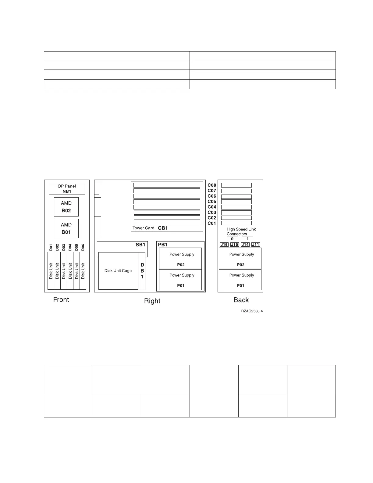
Locations — FC 5075 Expansion I/O Tower
For use by authorized service providers.
The following diagram shows FRU layout in the FC 5075 expansion Expansion I/O Tower. Use it with the
tables below. If you need address information, refer to Addresses — FC 5075 Expansion I/O Tower.
Figure 1. Locations for the FC 5075 Expansion I/O Tower
The following table gives the components available for callout on the FC 5075 Expansion I/O Tower. It
matches those components with the FRU containing the component. The other columns give location
information, CCIN information, a link to a remove and replace procedure, and additional information.
Table 1. FRU locations and failing components for FC 5075 Expansion I/O Towers
Possible failing
component FRU name Position
Type or CCIN
number (see the
Type, model, and
part number list)
Remove and
replace
procedure
Additional
comments
IOA PCI card C01 through C04,
C06, C07, C08
See the Type,
model, and part
number list.
Go to FC 5075 -
Cards
(concurrent).
Analyze hardware problems 299
 Loading...


