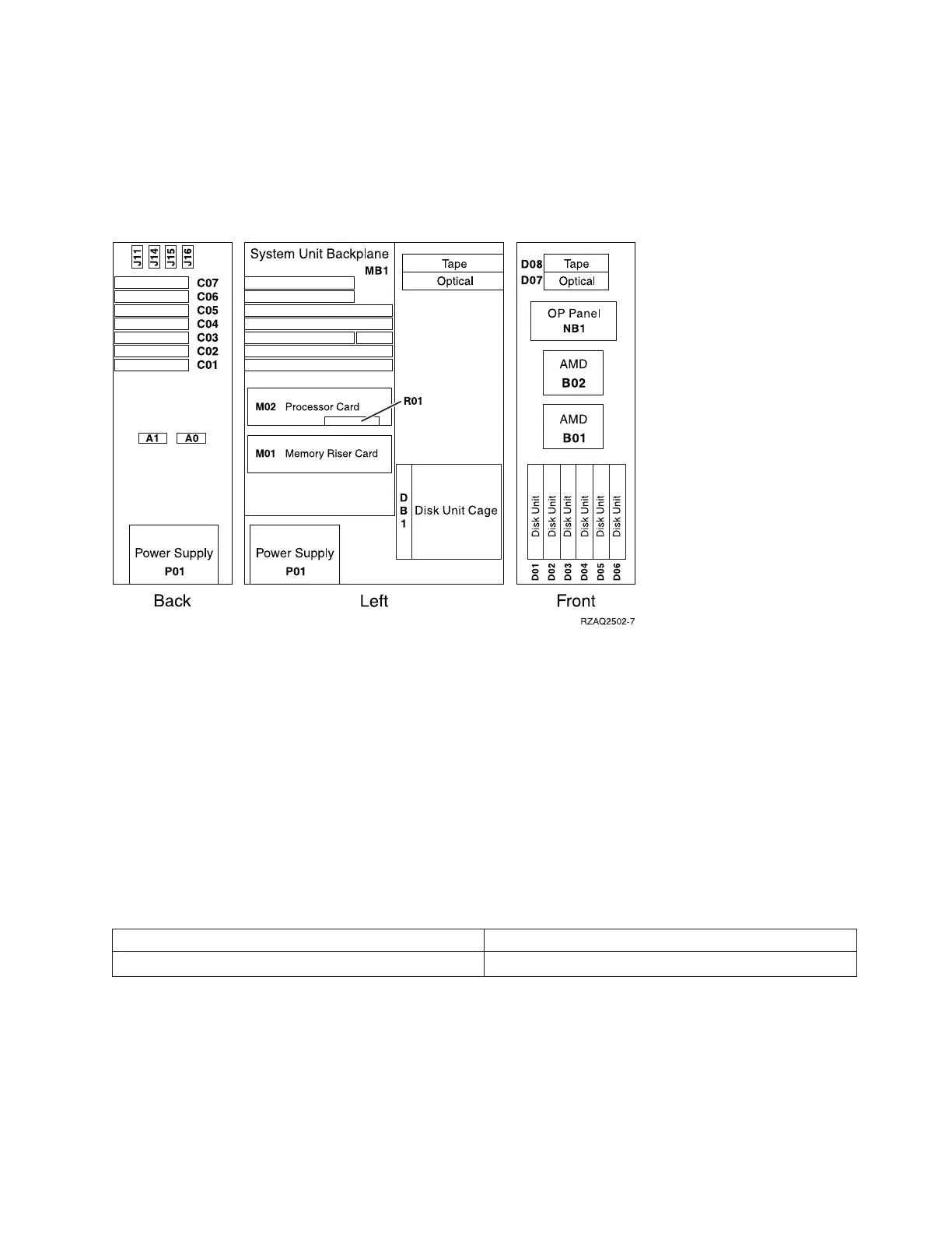
Model 810 system unit processor features 7428, 7430: The following diagram shows FRU layout in
the Model 810 (with processor features 7428, 7430) and the associated system unit expansion. Use it in
conjunction with the tables below. If you need address information, refer to Addresses — Models 800 and
810.
Figure 1. Model 810 system unit with processor features 7428, 7430
Notes:
1. The model 810 system unit contains one system PCI bus with one multi-adapter bridge. The bus
number is 0001.
2. There is an embedded CFIOP in the system unit backplane in position MB1.
3. The following table provides information necessary to identify the IOP to which IOAs are assigned.
v The left column indicates the domain in which IOA assignment is allowed.
v The right column is used to determine the IOP to which an IOA is assigned.
v The first position in the list must be an IOP. The remaining positions may be IOPs or IOAs. IOAs are
assigned to the first IOP located to their left in the list. Although IOAs can be manually reassigned
using SST/DST, the IOA assignments return to the default order after each IPL.
v J11 (remote power on); J14 (UPS); J15 (SPCN 0); J16 (SPCN 1).
Table 2. IOA assignment rules for MB1, C01-C07
Multi-adapter bridge domain / PCI bridge set IOA assignment rules
MB1, C01 - C07 MB1, C07, C01, C06, C05, C04, C03, C02
Table 3. FRU locations and failing components for Model 810 (Processor features 7428, 7430)
Analyze hardware problems 241
 Loading...


