To remove or replace the device board (DB1 and DB2):
1. Power off the expansion tower (see Power on/off the system and logical partitions).
2. Disconnect the power cord from the expansion tower.
3. Open the front cover. See FC 5074, FC 5079, FC 5094, FC 5294, FC 9079, FC 9094 - Covers.
4. From the front of the expansion tower, do the following:
a. Remove the EMC access plates from the disk unit enclosures that are located in front of the
backplane that you are replacing. (For location information, see Locations — FC 5074 Expansion
I/O Tower.) Press the surfaces of the two latching mechanisms together and tilt the top of the cover
away from the frame to remove it.
b. Record the locations of the disk units and then remove them from the disk unit enclosures that you
just uncovered.
Attention: The disk units are sensitive to electrostatic discharge (see Work with electrostatic
discharge-sensitive parts).
c. Remove the screws that hold the disk unit cage assembly to the frame.
d. Remove the two retaining screws that are located inside of the disk unit cage assembly (the top
right and bottom left corners).
e. Remove the disk unit cage assemblies.
f. Remove the screws that hold the DASD shelf to the frame.
g. Remove the DASD shelf from the frame.
5.
Remove the retaining screw that is holding the DASD board assembly to the frame.
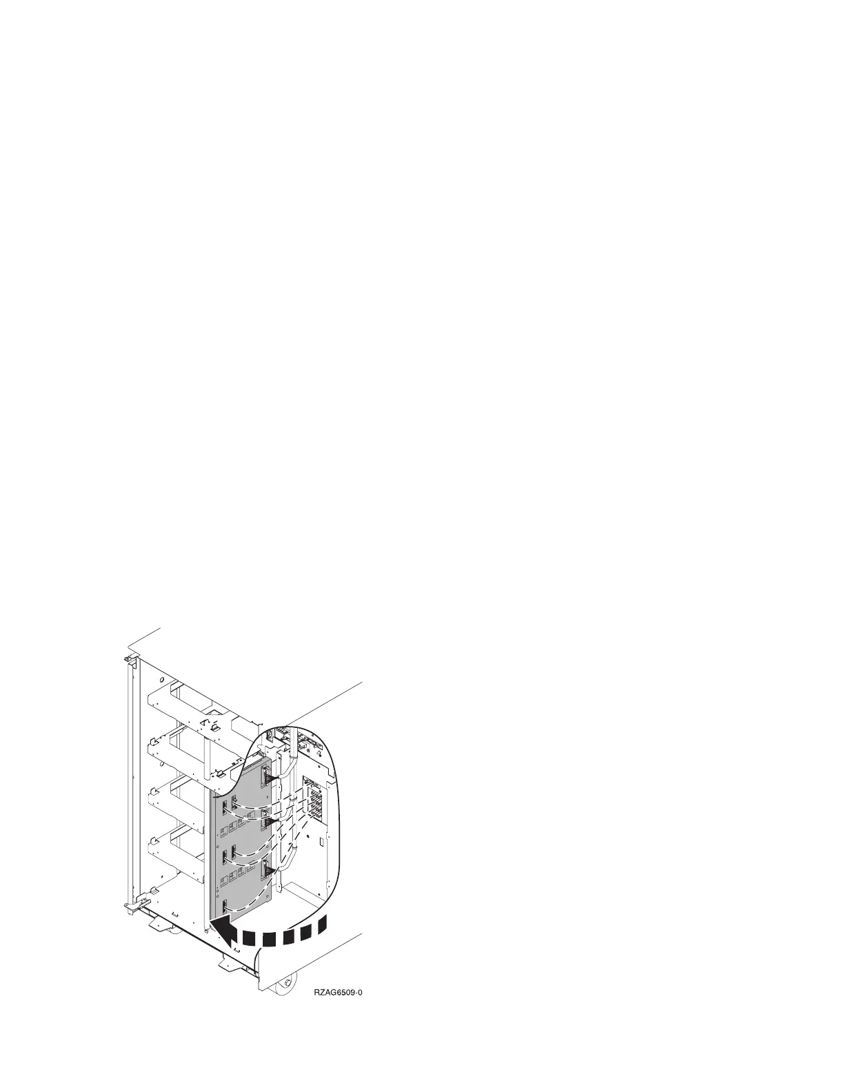
6. Pull the DASD board assembly out until it slides off the guide pins, then rotate the DASD board
assembly 90 degrees. Note the locations of the cables that are located on the backside of the board
assembly, and then remove them.
Note: Both ends of the ribbon cables are marked LH or RH, indicating that one end of the cable is
plugged in to either the left-hand (DB1) or right-hand (DB2) DASD board assembly. The other end of
the cable is plugged in to either the left-most (LH) or right-most (RH) DASD controller card. The cables
will crisscross in the center of the tower.
Figure 1. Device board cabling
Analyze hardware problems 143
 Loading...


