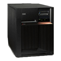
– For FC 5088 or FC 0588: Card positions C01 through C09 and C11 through C15 permit card level
concurrent maintenance using HSM. You can power down the individual card slot.
v
If the resource is the load source IOA or the load source IOP, or any other storage IOA/IOP with critical
DASD attached for the system, primary, or secondary partition, follow the on-screen instructions when
you use HSM to power down the IOP or IOA. Instructions to use functions 68 and 69 on the control
panel will be included.
v If the resource is the console IOA or the console IOP for the system or primary partition, you cannot
power down the domain.
v If the resource is the console IOA or the console IOP for a secondary partition, then power down the
secondary partition and follow the procedure from the primary partition.
CAUTION:
The circuit card contains lead solder. To avoid the release of lead (Pb) into the environment, do not
burn. Discard the circuit card as instructed by local regulations. (RSFTC234)
Attention: If removing the cover while powered on, errors may occur due to electromagnetic interference.
Attention: All cards are sensitive to electrostatic discharge. See Work with electrostatic
discharge-sensitive parts.
To remove or replace cards (concurrently):
1. From the Hardware Service Manager display, select Packaging hardware resources —> Hardware
contained in packaging for the frame ID that you are working on.
2. Find the card position for the IOA or IOP that you are removing and select Concurrent maintenance.
Attention: If multiple resources are shown with the same card position, one or more of these
resources will show a status of Missing (″?″ after the description). Only one resource will be listed as
not missing. Select this resource for the concurrent maintenance operation.
3. A listing of the power domain is shown. Find the IOA or IOP that you are removing and select Power
off domain. Everything within the IOA’s or IOP’s power domain will be powered off .
4. To see the status of the power domain, select Display power status.
5. Find the IOA or IOP that you are removing and select Toggle LED blink off/on.
6. Remove the cover to access the card that you are removing from the system. See FC 5078, FC
0578, FC 5088, FC 0588 - Covers.
7. Look at the power LED for the card that you are removing to ensure that it is powered off. The power
LED is located above or in front of the card slot. If the LED is blinking multiple times per second
(rapidly) or it is off, then the card is powered off.
8. Remove the rear cover. See FC 5078, FC 0578, FC 5088, FC 0588 - Covers.
9. Remove the EMC access plate, that is located directly above the card enclosure, by removing the
three thumbscrews and pulling the access plate towards you.
10. Disconnect and label any cables from the card that you wish to remove.
11. Turn the latch counter-clockwise and lift up on the black latch to release the card.
12. Remove the card by gently pulling it out.
13. Install the card in to the system by reversing the card removal procedure.
14. Select Power on domain for the IOA or IOP that you are installing.
Note: To the right of the description field you will see one or both of the following symbols displayed.
Symbol Indication
* Indicates the location to which the system will assign the resource.
> Indicates the location to which the resource was last assigned.
15. Press Enter. The Work with Controlling Resources display will appear.
166 Hardware (Remove and Replace; Part Locations and Listings)
 Loading...


