Notes:
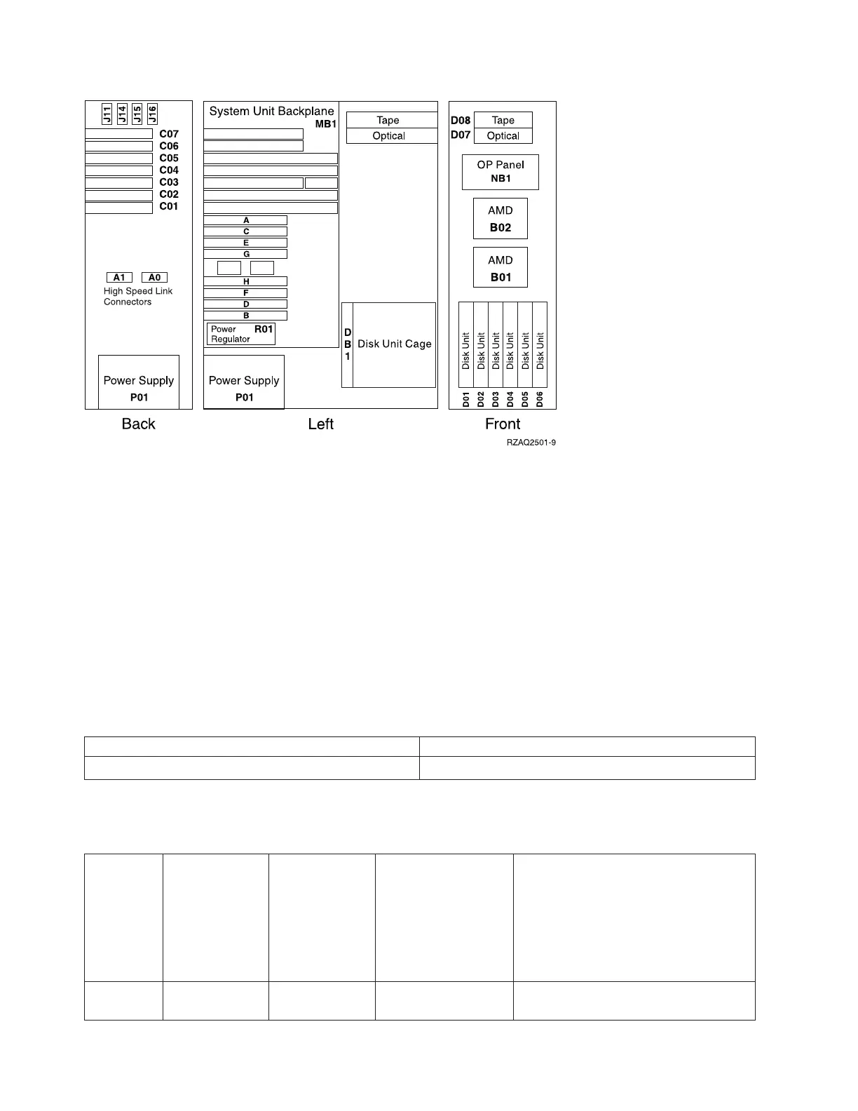
1. The model 270 system unit contains one system PCI bus with one multi-adapter bridge. The bus
number is 0001.
2. There is an embedded CFIOP in the system unit backplane in position MB1.
3. Memory DIMMS are placed in pairs when more than one DIMM is present. Use the order A-B, C-D,
E-F, then G-H.
4. The following table provides information necessary to identify the IOP to which IOAs are assigned.
v The left column indicates the domain in which IOA assignment is allowed.
v The right column is used to determine the IOP to which an IOA is assigned.
v The first position in the list must be an IOP. The remaining positions may be IOPs or IOAs. IOAs are
assigned to the first IOP located to their left in the list. Although IOAs can be manually reassigned
using SST/DST, the IOA assignments return to the default order after each IPL.
Table 2. IOA assignment rules for MB1, C01-C07
Multi-adapter bridge domain / PCI bridge set IOA assignment rules
MB1, C01 - C07 MB1, C07, C01, C06, C05, C04, C03, C02
Table 3. FRU locations and failing components for Model 270 (Processor features 22A2, 22A4,
22A5, 2301, 2302, 2422)
Position FRU name
Possible failing
component
Type, CCIN, or part
number (use the
Type, model, and
part number list to
determine the part
number when the
type or CCIN are
given.)
Remove and replace/recovery
procedure
C01 PCI card IOA See the Type, model,
and part number list.
Go to Models 270, 800, and 810 - Cards
(dedicated).
228 Hardware (Remove and Replace; Part Locations and Listings)
 Loading...


