Page 48 Setup and Assembly Manual
C Maintenance, Tests and Troubleshooting
C.1 Separating Device Cover from Device Body
Disconnect the power cable before doing any maintenance to the
device.
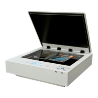
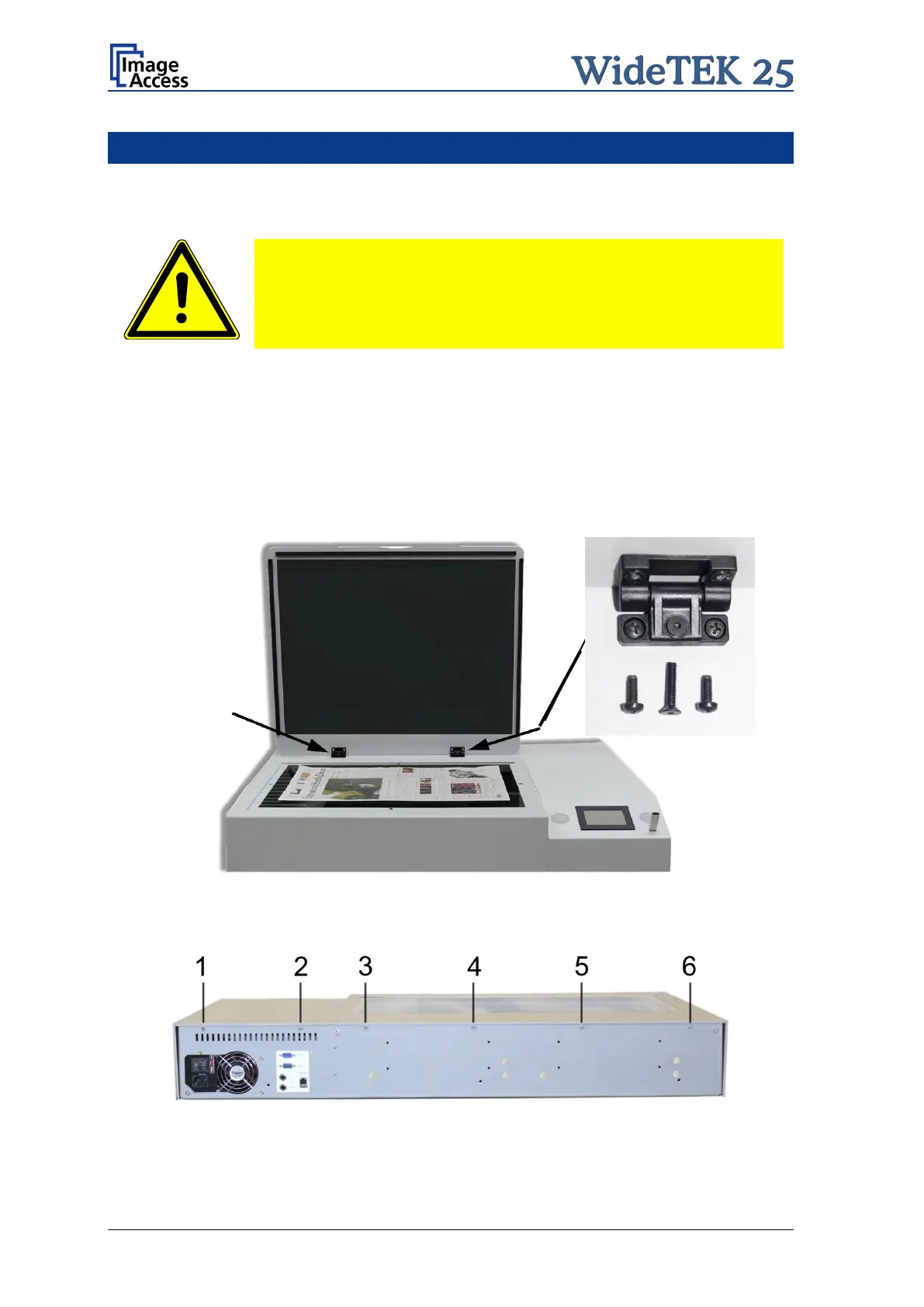
At first remove the glass plate cover. Two hinges hold the glass plate cover at the device
cover.
Each hinge has three screws which hold it at the device cover. Use a Phillips screwdriver
to remove the two screws on the left and right position. Use an Allen head screw driver,
size 2.5 mm, to remove the screw in the middle position of each hinge.
Note: Use the countersunk Allen head screw only at the middle position of the hinges!
Picture 42: Arrows point on the hinges to be removed
In the next step remove six hexagon head screws at the back side of the device body.
Picture 43: Hexagon head screws to be removed
 Loading...