Setup and Assembly Manual Page 49
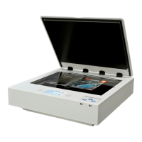
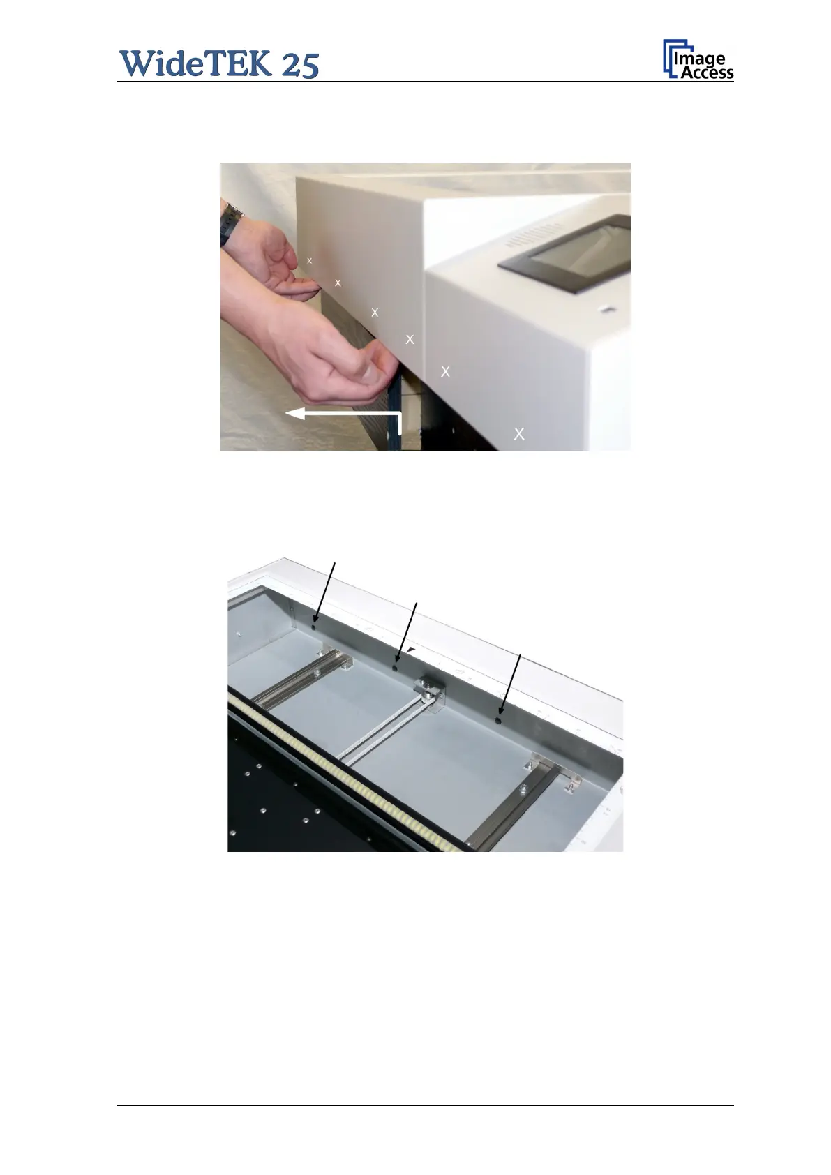
After the six screws have been removed the device cover must be lifted and pulled a little
at the front side as shown in the picture below.
Picture 44: Lift and pull the device cover
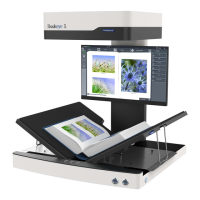
The device cover has six alignment pins on its front side. For easy orientation the position
of the alignment pins are marked in the above picture by the six white crosses.
They are visible when looking from above through the glass plate.
Picture 45: Arrows mark three of six alignment pins
While pulling at the device cover, look through the glass plate and stop pulling when the
alignment pins are out of their boreholes.
 Loading...