Table of Pictures
Picture 1: Transport box opened....................................................................................... 14
Picture 2: Floor stand box opened .................................................................................... 15
Picture 3: Assembling material.......................................................................................... 15
Picture 4: Technical drawing of floor stand .......................................................................16
Picture 5: Floor stand components.................................................................................... 17
Picture 6: Side pillar in foot profile.....................................................................................18
Picture 7: Traverse inserted into foot bracket.................................................................... 18
Picture 8: Inserting screws with washer ............................................................................19
Picture 9: Bottom and side components assembled ......................................................... 19
Picture 10: Top bracket on vertical leg.............................................................................. 20
Picture 11: Upper traverse inserted................................................................................... 20
Picture 12: Inserting the rod ..............................................................................................21
Picture 13: Two persons lifting the scanner out of the transport box ................................21
Picture 14: Lift the scanner to remove the foam rubber element ...................................... 22
Picture 15:Removing foam rubber element and cardboard element................................. 22
Picture 16: Bottom side, front side left............................................................................... 23
Picture 17: Bottom side, back side left ..............................................................................23
Picture 18: Fastening the scanner onto the floor stand.....................................................23
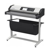
Picture 19: WideTEK 36 placed on floor stand, ready to use............................................ 24
Picture 20: Connectors at WideTEK 36............................................................................. 26
Picture 21: Start menu screen........................................................................................... 27
Picture 22: Touch panel while shut down in progress....................................................... 28
Picture 23: Keyboard with capital letters ...........................................................................29
Picture 24: Keyboard with lower case letters .................................................................... 29
Picture 25: Self Test 1 menu............................................................................................. 30
Picture 26: Network setup .................................................................................................31
Picture 27: Numeric key pad .............................................................................................31
Picture 28: Confirm changes............................................................................................. 31
Picture 29: White Balance screen .....................................................................................33
Picture 30: Progress indicator ...........................................................................................33
Page 10 Setup and Assembly Manual
 Loading...