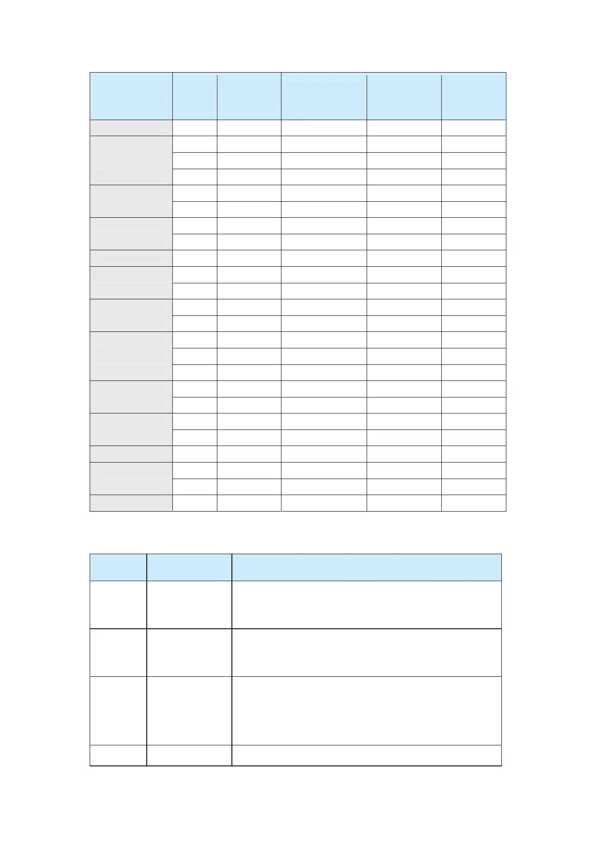
CS500 Model
MCCB
(A)
Contactor
(A)
Cable of Input
Side Main Circuit
(mm
2
)
Cable of
Output Side
Main Circuit
(mm
2
)
Cable of
Control
Circuit
(mm
2
)
CS500-4T3.7GB 16 10 2.5 2.5 1.0
CS500-4T5.5GB 32 25 4.0 4.0 1.0
CS500-4T7.5GB 40 32 4.0 4.0 1.0
CS500-4T11GB 63 40 4.0 4.0 1.0
CS500-4T15GB 63 40 6.0 6.0 1.0
CS500-4T18.5GB 100 63 6 6 1.5
CS500-4T22GB 100 63 10 10 1.5
CS500-4T30GB 125 100 16 10 1.5
CS500-4T37G 160 100 16 16 1.5
CS500-4T45G 200 125 25 25 1.5
CS500-4T55G 200 125 35 25 1.5
CS500-4T75G 250 160 50 35 1.5
CS500-4T90G 250 160 70 35 1.5
CS500-4T110G 350 350 120 120 1.5
CS500-4T132G 400 400 150 150 1.5
CS500-4T160G 500 400 185 185 1.5
CS500-4T185G 600 600 150 x 2 150*2 1.5
CS500-4T200G 600 600 150 x 2 150*2 1.5
CS500-4T220G 600 600 150 x 2 150*2 1.5
CS500-4T250G 800 600 185 x 2 185*2 1.5
CS500-4T280G 800 800 185 x 2 185*2 1.5
CS500-4T315G 800 800 150 x 3 150*3 1.5
CS500-4T355G 800 800 150 x 4 150*4 1.5
CS500-4T400G 1000 1000 150 x 4 150*4 1.5
3.2.2 Usage Description of Peripheral Electrical Devices
Table 3-3 Description of peripheral electrical devices
Device
Installation
Location
Function Description
Molded case
circuit
breaker
(MCCB)
At the front end of
the input circuit
Break off the power supply when over-current occurs on
downstream devices.
Contactor
Between the MCCB
and the input side
of the AC drive
Start and stop the AC drive.
Do not start or stop the AC drive frequently by switching on and off
the contactor (less than twice per minute) or directly start the AC
drive.
AC input
reactor
On the input side of
the AC drive
z Improve the power factor on the input side.
z Eliminate the high order harmonics on the input side
effectively and prevent other device from being damaged due
to distortion of voltage wave.
z Eliminate the input current unbalance due to unbalance
between the power phases.
EMC input On the output side z Reduce the external conduction and radiation interference of
efesotomas
on.com
 Loading...