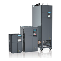
Figure 4-7 Frequency set by the main frequency source
0
0-10 V
1
Ÿ
ź
Retentive at
power failure
0-10 V
4-20 mA
JP
3
F0-08
0-10 V
AI1
AI2
AI3
On
extension
card
F4-04 = 30
DI5
Pulse input
2
3
4
5
F4-00 to F4-04
= 12/13/14/15
Multi-speed
6
Analog
DI1 to DI10
FC-00 to FC-07
(frequency for
each segment)
Reserved
H1000
register
Communication
Host
computer
7
8
9
F4-13
to F4-17
F4-18
to F4-22
F4-23
to F4-27
F4-29
to F4.32
FD-00 to FD-05
(communication
configuration)
Digital setting
Main
frequency
source X
Reserved
F0-03
(Main
frequency
source X)
Analog
Analog
You can change the main frequency source any time by modifying the function codes. The
function code corresponding to each frequency source is provided in the preceding figure.
During the setting, view the detailed function code description.
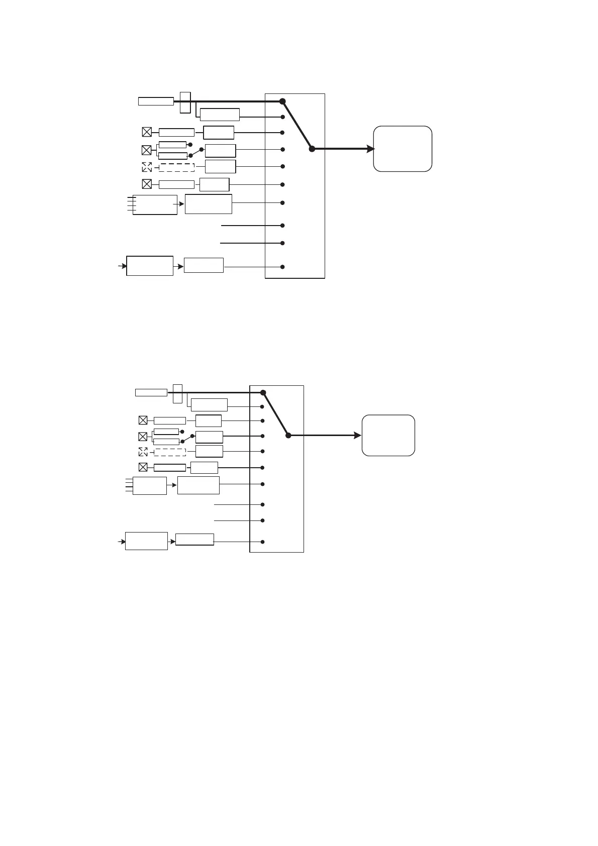
4.5.2 Frequency Setting With the Auxiliary Frequency Source
There are eight types of auxiliary frequency sources, and you can select one in F0-04.
Figure 4-8 Frequency set by the auxiliary frequency source
0
0-10 V
1
Ÿ
ź
Retentive at
power failure
0-10 V
4-20 mA
JP
3
F0-08
0-10 V
AI1
AI2
AI3
On expansion
card
F4-04 = 30
DI5
Pulse input
2
3
4
5
F4-00 to
F4-09 =
12/13/14/15
Multi-speed
6
Analog
Analog
DI1 to DI10
FC-00 to FC-07
(frequency for
each segment)
Reserved
H1000
register
Communication
Host
computer
7
8
9
F4-13 to
F4-17
F4-18
to F4-22
F4-23
to F4-28
F4-29
to F4.32
Analog
FD.00 to FD.05
(communication
configuration)
Digital setting
Auxiliary
frequency
source Y
Reserved
F0-04
(Auxiliary
frequency
source Y)
In actual use, the relationshhip between the target running frequency and the main and
auxiliary frequency sources is set in F0-07, as follows:
1. Main frequency source X: The main frequency source is directly used to set the target
running frequency.
2. Auxiliary frequency source Y: The auxiliary frequency source is directly used to set the
target running frequency.
3. Superposition of X and Y
4. Frequency switchover: A DI terminal is used to switch over between the preceding three
frequency setting channels.
An external DI signal (the function of the DI terminal is set to 12) is used to dynamically
switch over between the preceding frequency setting channels. As shown in the following
figure, the overstriking line indicates the default setting. For details on how to set the
related function codes, see the detailed description of these function codes.
Figure 4-9 Switchover between frequency setting channels
efesotomas
on.com
 Loading...