the AC drive and even cause fire.
3. Terminals (+), PB for connecting the braking resistor:
z The connecting terminals of the braking resistor are effective only for the AC drive of
30 kW or below with a built-in braking unit.
z The cable length of the braking resistor must be less than 5 m. Otherwise, it may
damage the AC drive.
4. Terminals P, (+) for connecting the external reactor:
For the AC drive of 75 kW or above, remove the jumper across terminals P and (+) and
install the reactor between the two terminals.
5. Output terminals U, V, W of the AC drive:
z The output side of the AC drive must not be connected with a capacitor or surge
absorber. Otherwise, it may cause frequent AC drive protection or even damage the
AC drive.
z If the motor cable is too long, electrical resonance is generated due to the impact of
distributed capacitance. This damages motor insulation or generates large leakage
current that causes AC drive over-current protection. If the motor cable is ove-50 m
long, install an AC output reactor nearby the AC drive.
6. Grounding terminal
PE:
z This terminal must be grounded reliably. The resistance of the grounding cable must
be less than 0.1 ȍ. Otherwise, it may cause fault or damage to the AC drive.
z Do not share the earth terminal and the N terminal of the power supply zero line.
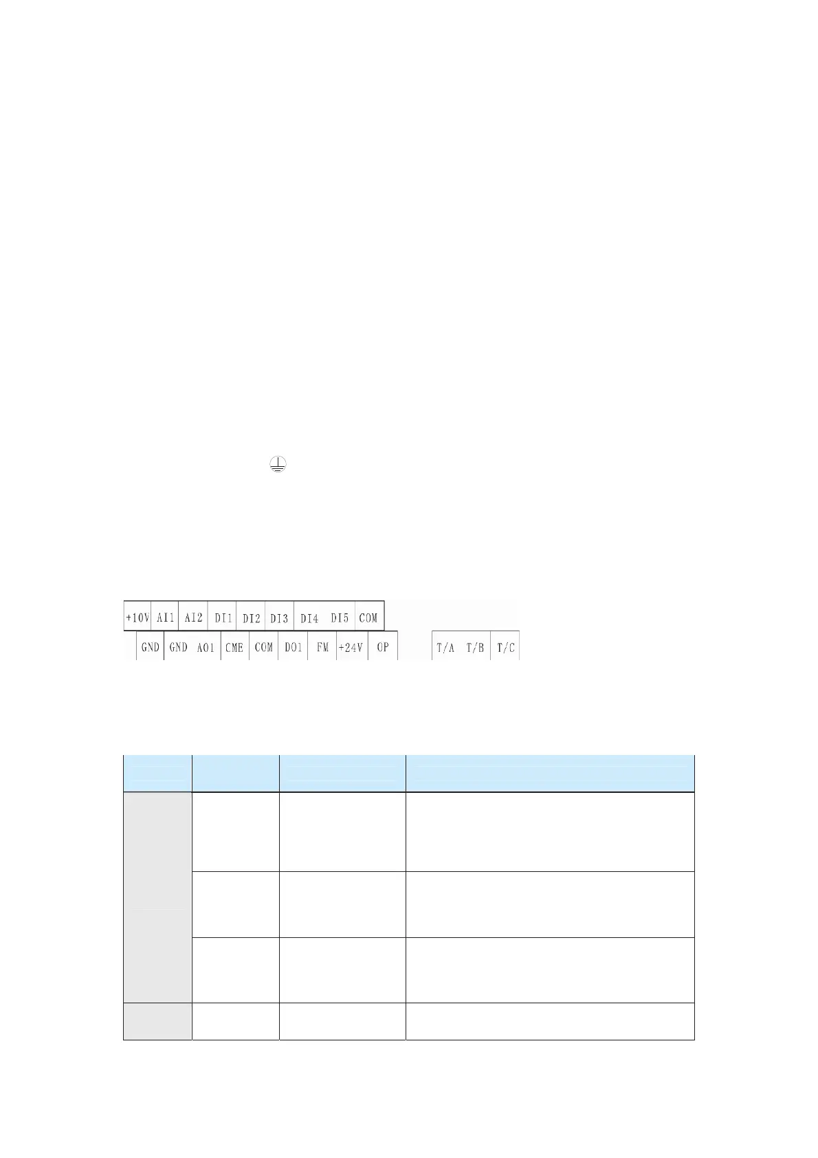
3.2.5 Control Circuit Terminals and Wiring
Terminal Arrangement
Function Description
The following table describes the terminals of the control circuit.
Table 3-5 Descriptions of control circuit terminals
Type
Terminal
Symbol
Terminal Name Function Description
+10V-GND
External +10V
power supply
Provide +10 V power supply externally. Generally,
it provides power supply to the external
potentiometer with resistance range of 1 kȍ to 5
kȍ.
Maximum output current: 10 mA
+24V-COM
External +24V
power supply
Provide +24 V power supply externally. Generally,
it provides power supply to DI/DO terminals and
external sensors.
Maximum output current: 200 mA
Power
supply
OP
Input terminal of
external power
supply
It is connected to +24V by default.
When DI1 to DI5 needs to be driven by external
signals, OP needs to be connected to the external
power supply and be disconnected from +24V.
AI
AI1-GND AI1
1. Input voltage range: 0–10 VDC
2. Input impedance: 100 kȍ
efesotomas
on.com
 Loading...