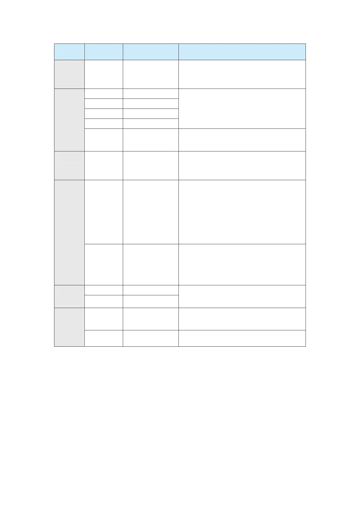
Type
Terminal
Symbol
Terminal Name Function Description
AI2-GND AI2
1. Input range: 0–10 VDC/4–20 mA, decided by
jumper J3 on the control board
2. Input impedance: 100 kȍ (voltage input), 500 ȍ
(current input)
DI1-COM DI1
DI2-COM DI2
DI3-COM DI3
DI4-COM DI4
1. Optical coupling isolation, compatible with dual
polarity input
2. Input impedance:3.3 kȍ
3. Voltage range for level input: 9–30 V
DI
DI5-COM
High-speed pulse
input
Having features of DI1 to DI4, it can be also used
as the channel for high-speed pulse input.
Maximum input frequency:50 kHz
AO AO1-GND AO1
1. Voltage output or current output determined by
jumper J4.
2. Output voltage range: 0–10 V
3. Output current range: 0–20 mA
DO1-CME DO1
1. Optical coupling isolation, dual polarity
open-collector output
2. Output voltage range: 0–24 V
3. Output current range: 0–50 mA
Note that CME and COM are internally isolated,
but they are short-circuited externally by using a
jumper at factory delivery (DO1 is driven by +24V
by default in this case). If DO1 needs to be driven
by external power supply, remove the jumper.
DO
FM-COM
High-speed pulse
output
It is restricted by F5-00 (FM terminal output mode
selection).
z As high-speed pulse output, the maximum
frequency reaches 50 kHz.
z As open-collector output, its specification is
the same as that of DO1.
T/A-T/B NC terminal
Relay
output
T/A-T/C NO terminal
Contact driving capacity:
250 VAC: 3 A, COSø = 0.4
30 VDC: 1 A
J1
Extension card
interface
Used as the Interface of 28-pin terminal and
optional card (I/O extension card, Modbus
communication card and various bus cards).
Auxiliary
interface
CN3
External operation
panel interface
Used as the interface for connecting the external
operation panel or LCD operator.
Wiring Description
1. Wiring of AI terminals
Weak analog voltage signals are easy to suffer external interference, and therefore the
shielded cable must be used and the cable length must be less than 20 m, as shown in
following figure.
efesotomas
on.com
 Loading...