CS500
Maximum Wiring Size of
the Power Terminal
Torque of the
Torque Driver
CS500 mm
2
AWG kgf.cm
T7.5GB 4.0 12 28±0.5
T11GB 4.0 12 28±0.5
T15GB 6.0 10 28±0.5
Function Description
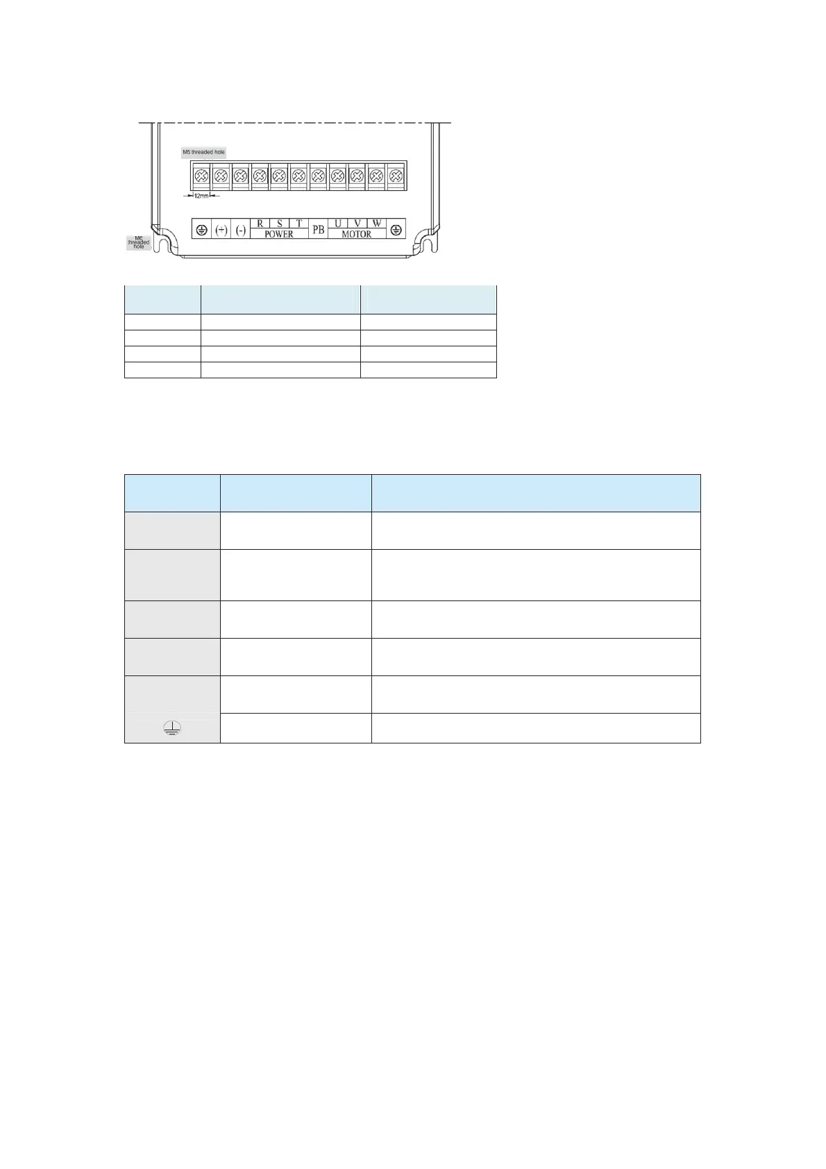
The following table describes the power terminals of the AC drive main circuit.
Table 3-4 Descriptions of the power terminals on the main circuit
Terminal
Symbol
Terminal Name Description
R, S, T
Three-phase power
input terminals
Used as the AC input points of three-phase power supply
(+), (-)
Positive and negative
terminals of DC bus
Used as the input points of the common DC bus
(connection points of the external braking unit for models
of 37 kW or above)
(+), PB
Terminals for connecting
the braking resistor
Used as the connection points of the braking resistor for
models of 30 kW or below
P, (+)
Terminals for connecting
the external reactor
Used as connection points for the external reactor
U, V, W
AC drive output
terminals
Used for connecting the three-phase motor
Grounding terminal Used for grounding
Wiring Description
1. Power input terminals:
The cable connection on the input side of the AC drive has no phase sequence
requirement.
2. (+), (-) terminals of the DC bus:
z Terminals (+) and (-) of DC bus have residual voltage after power-off. Start wiring only
after the CHARGE indicator becomes off and ensure that the voltage is less than 36 V.
Otherwise, electric shock may result.
z When selecting external braking unit for the AC drive of 37 kW or above, do not
reverse poles (+) and (-). Otherwise, it may damage the AC drive and even cause a
fire.
z The cable length of the braking unit must not be longer than 10 m. Use twisted pair
wire or pair wires for parallel connection.
z Do not connect the braking resistor directly to the DC bus. Otherwise, it may damage
efesotomas
on.com
 Loading...