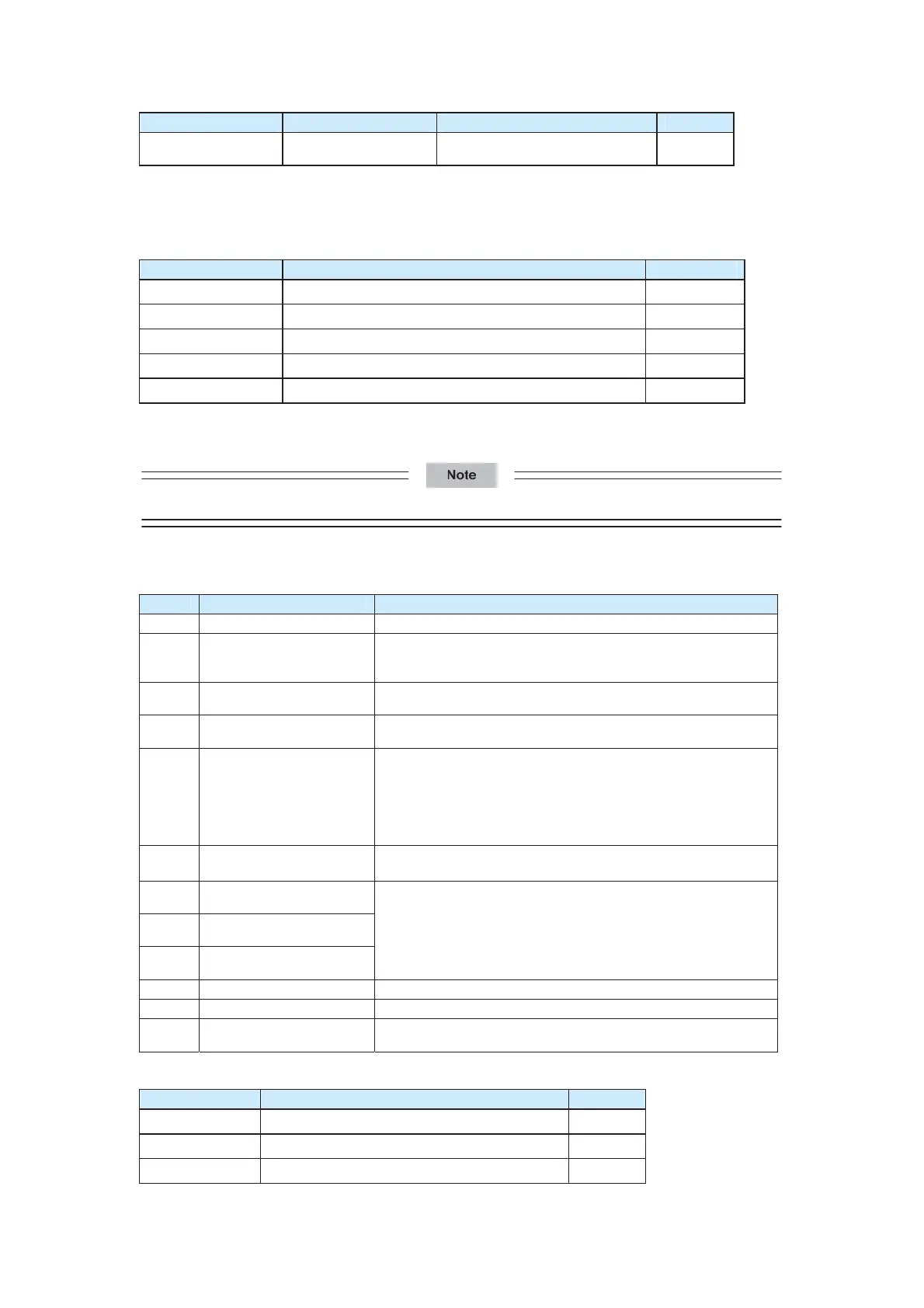
Function Code Parameter Name Setting Range Default
F5-00
FM terminal output
mode selection
0: Pulse output (FMP)
1: Open-collector output (FMR)
0
The FM terminal is a programmable multiplexing terminal. It can be used as high-speed
pulse output (FMP), with maximum frequency of 50 kHz. For relevant FMP functions, see
the description of F5-06. The FM terminal can also be used as open-collector output
(FMR). For the FMR function, see the description of F5-01.
Function Code Parameter Name Default
F5-01 FMR function selection (open-collector output terminal)
0
F5-02
Control board relay1 output selection (T/A-T/B-T/C)
21
F5-03
Extension card relay2 output selection (P/A-P/B-P/C)
0
F5-04
DO1 function selection (open-collector output terminal)
2
F5-05
Extension card DO2 function selection
0
If the CS500 is connected to the relay card CS70RC1, F5-03 is used to control relay K3.
The function of K3 is the same as that of other relays.
Relay1 refers to T/A-T/B-T/C and relay2 refers to P/A-P/B-P/C.
The following table lists the functions of the output terminals.
Table 6-3 Functions of the output terminals
Value Function Description
0
No output
The output terminal has no function.
1
AC drive running
It indicates that the AC drive is running and has output
frequency (can be zero), and the terminal outputs the ON
signal.
2
Fault output (stop)
When the AC drive stops due to occurrence of a fault, the
terminal outputs the ON signal.
3
Frequency-level
detection (FDT) output
For details, see the description of F8-19 and F8-20.
6
Motor overload
pre-warning
Before taking the protection action, the AC drive judges
whether the motor will be overloaded according to the motor
overload pre-warning threshold. If the overload pre-warning
threshold is reached, the terminal outputs the ON signal. For
more details, see motor overload parameters of F9-00 to
F9-02.
7
AC drive overload
pre-warning
The terminal outputs the ON signal 10s before the AC drive
overload protection action.
8
Motor 1 connection
indication
9
Motor 2 connection
indication
10
Motor 3 connection
indication
Indicate that the corresponding motor is connected.
20
Communication setting
See the description in the communication protocol.
21
Brake output
Control the brake output relay.
22
Low-speed shaft brake
output
Control auxiliary clamp output relay.
Function Code Parameter Name Default
F5-06
FMP function selection (pulse output terminal)
0
F5-07
AO1 function selection (AO1)
0
F5-08
AO2 function selection (AO2)
1
efesotomas
on.com
 Loading...