Intel® Server Board S1200V3RP TPS Functional Architecture
Revision 1.2
The memory slots are named as Slot1 and Slot2 on each channel. Slot1 is the farthest
from the processor socket.
DIMMs are named to reflect the channel and slot in which they are installed:
- Channel A, Slot1 is DIMM_A1.
- Channel A, Slot2 is DIMM_A2.
- Channel B, Slot1 is DIMM_B1.
- Channel B, Slot2 is DIMM_B2.
3.3.1 Supported Memory
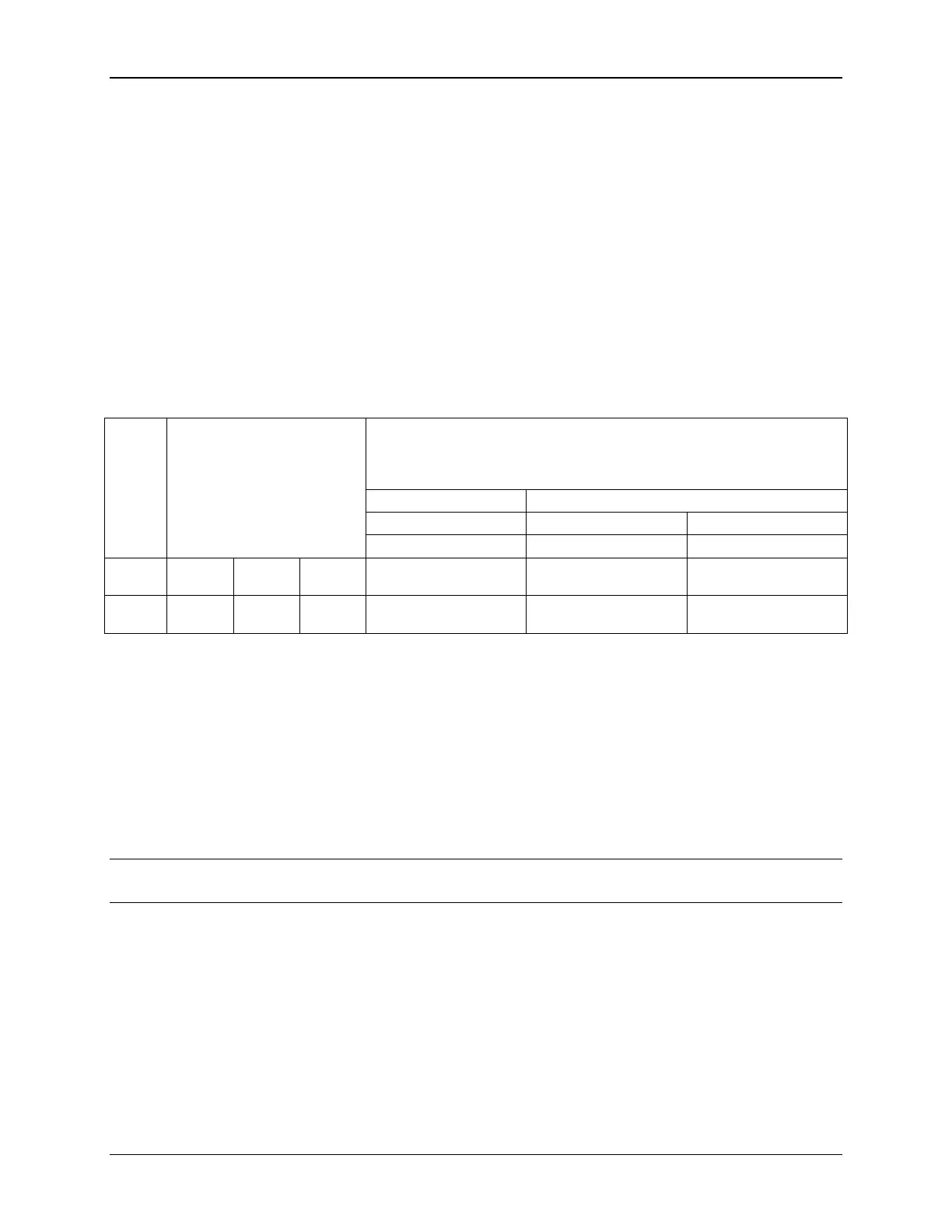
Single Ranked x8 unbuffered ECC
Dual Ranked x8 unbuffered ECC
Table 2. UDIMM Support Guidelines
Ranks
Per
DIMM
and
Data
Width
Speed (MT/s) and Voltage Validated by
Slot per Channel (SPC) and DIMM Per Channel (DPC)
Notes:
1. No support for RDIMMs.
2. No support for SODIMM.
3. All channels in a system run at the fastest common frequency.
4. Mixing ECC and non-ECC UDIMMs anywhere on the platform is not supported.
5. Static CLTT supported using BMC (requires ECC DIMMs with thermal sensor).
3.3.1.1 Memory Population Rules
Note: Although mixed DIMM configurations are supported, Intel
®
only performs platform
validation on systems that are configured with identical DIMMs installed.
The processor provides two channels of memory, each capable of supporting up to two DIMMs.
DIMMs are organized into physical slots on DDR3L memory channels that belong to
processor sockets.
The silk screened DIMM slot identifiers on the board provide information about the
channel. For example, DIMM_A1 is the first slot on Channel A on processor.
Slot1 must be populated first before Slot2, on either channel.
Channel A and Channel B are independent and are not required to have the same
number of DIMMs installed. Either channel may be used for a single-DIMM configuration.
 Loading...


