On-board Connector/Header Overview Intel® Server Board S1200V3RP TPS
Revision 1.2
8.4.5 NIC Activity LED Support
The Front Control Panel includes an activity LED indicator for each on-board Network Interface
Controller (NIC). When a network link is detected, the LED will turn on solid. The LED will blink
once network activity occurs at a rate that is consistent with the amount of network activity that
is occurring.
8.4.6 Hard Drive Activity LED Support
The drive activity LED on the front panel indicates drive activity from the on-board hard disk
controllers. The server board also provides a header giving access to this LED for add-in
controllers.
8.4.7 System Status LED Support
The System Status LED is a bi-color (Green/Amber) indicator that shows the current health of
the server system. The system provides two locations for this feature; one is located on the
Front Control Panel, the other is located on the back edge of the server board, viewable from
the back of the system. Both LEDs are tied together and will show the same state. The System
Status LED states are driven by the on-board platform management sub-system.
8.5 I/O Connectors
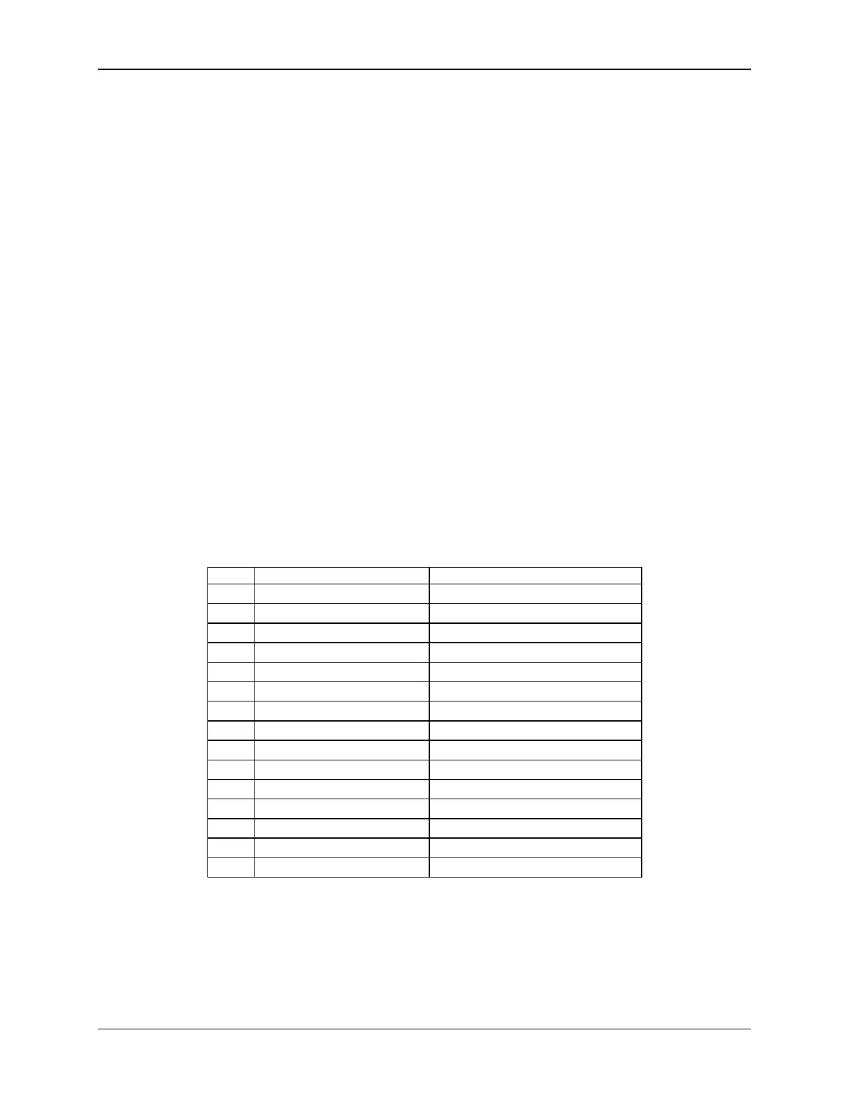
8.5.1 VGA Connector
The following table details the pin-out definition of the VGA connector (J7A1).
Table 42. VGA Connector Pin-out (J7A1)
Red (analog color signal R)
Green (analog color signal G)
Blue (analog color signal B)
 Loading...


