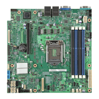
Intel® Server Board S1200V3RP TPS Functional Architecture
Revision 1.2
3.4.6.2 Legacy USB Support
The BIOS supports PS/2 emulation of USB keyboards and mouse. During POST, the BIOS
initializes and configures the root hub ports and searches for a keyboard and/or a mouse on the
USB hub and then enables the devices that are recognized.
3.4.6.3 eUSB SSD Support
The server board provides support for a low profile eUSB SSD storage device. A 2mm 2x5-pin
connector labeled eUSB SSD near the rear I/O section of the server board is used to plug this
small flash storage device into.
eUSB SSD features include:
Two wire small form factor Universal Serial Bus 2.0 (Hi-Speed USB) interface to host
Read Speed up to 35 MB/s and write Speed up to 24 MB/s
Capacity range from 256 MB to 32 GB
Support USB Mass Storage Class requirements for Boot capability
3.4.7 Gigabit Ethernet Controller
Network connectivity is provided by means of two onboard Intel
®
Ethernet Controller I210
providing up to two 10/100/1000 Mb Ethernet ports. The Intel
®
Ethernet Controller I210 is single,
compact, low-power components that offer a fully-integrated Gigabit Ethernet Media Access
Control (MAC) and Physical Layer (PHY) port. The Intel
®
Ethernet Controller I210 uses the PCI
Express* architecture from the Intel
®
C220 series PCH and provides a single-port
implementation in a relatively small area so it can be used for server and client configurations as
a LAN on Motherboard (LOM) design.
External interfaces provided on the I210:
PCIe Rev. 2.0 (2.5 GHz) x1
MDI (Copper) standard IEEE 802.3 Ethernet interface for 1000BASE-T, 100BASETX,
and 10BASE-T applications (802.3, 802.3u, and 802.3ab)
NC-SI or SMBus* connection to a Manageability Controller (MC)
EEE 1149.1 JTAG (note that BSDL testing is NOT supported)
Each Ethernet port drives two LEDs located on each network interface connector. The LED at
the right of the connector is the link/activity LED and indicates network connection when on, and
transmit/receive activity when blinking. The LED at the left of the connector indicates link speed
as defined in the following table.
Table 9. External RJ45 NIC Port LED Definition

 Loading...