Platform Management ArchitectureIntel® Server Board SE7520BD2 Technical Product Specification
114 Revision 1.3
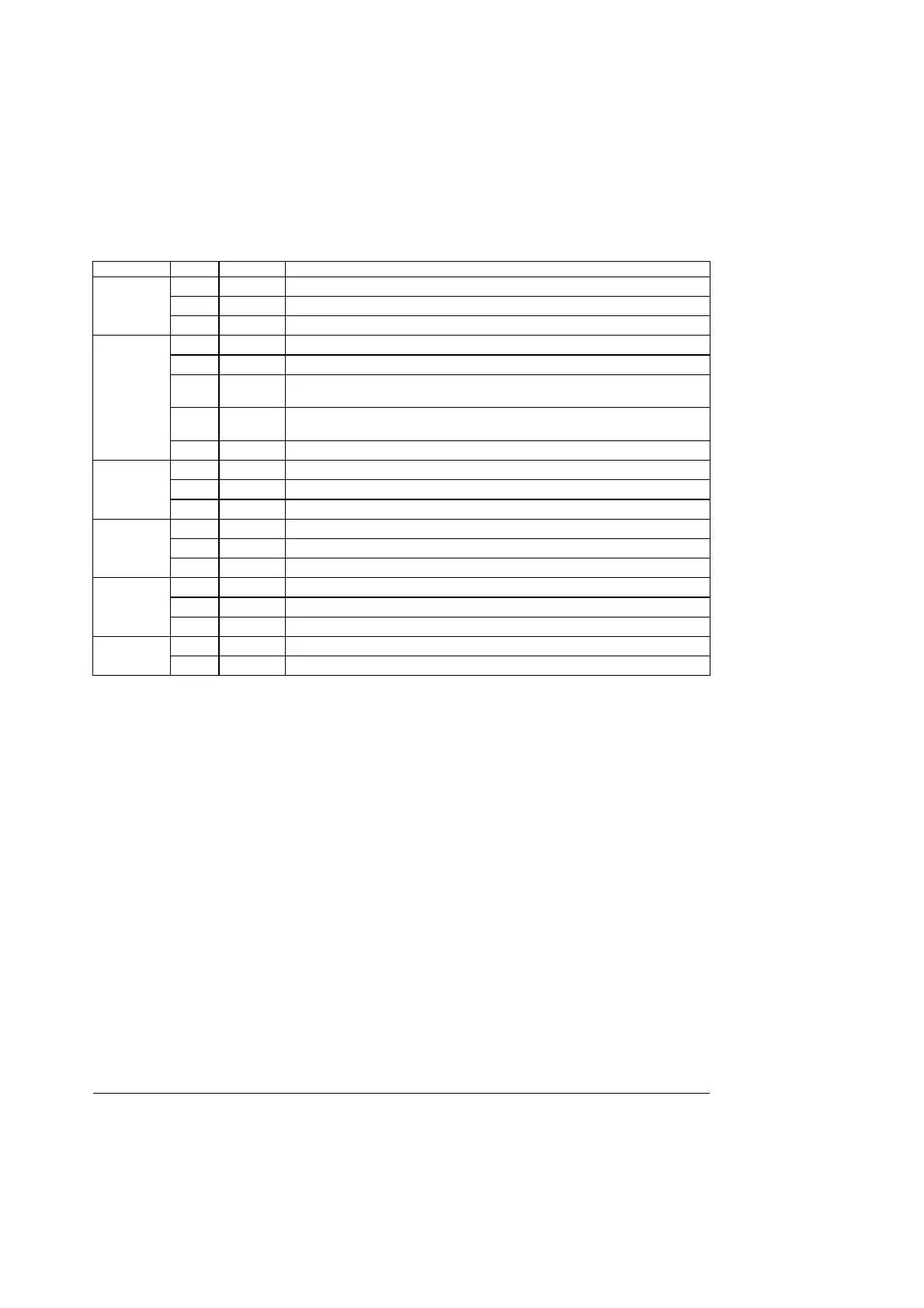
Table 54. Front Panel Color Attributes
Name Color Condition Description
Green ON Power On
Green BLINK Sleep (S1)
Power/Sleep
- OFF Power Off (also S4)
Green ON System Ready / No Alarm
Green BLINK System Ready but degraded: some CPU Fault, DIMM killed
Amber
ON
Critical Alarm: critical power module failure, critical fan failure, voltage (power
supply), critical temperature and voltage
Amber
BLINK
Non-critical Alarm: redundant fan failure, redundant power module failure, non-
critical temperature and voltage
Status
- OFF System Not Ready: POST error/NMI event/CPU or terminator missing
Green BLINK Hard Disk Drive Access
Amber ON HDD Fault
HDD
- OFF No Access and No HDD Fault
Green ON LAN Link / No Access
Green BLINK LAN Access
LAN#1-
Activity
- OFF Idle
Green ON LAN Link / no Access
Green BLINK LAN Access
LAN#2-
Activity
- OFF Idle
Blue BLINK Unit Selected for Identification
Identification
- OFF No Identification
Requirements:
• To support the front panel connectivity, a 2x17 0.1-inch pitch non-shrouded
polarized header is required. The first 24 pins (2x12) follow the SSI-EEB
Specification for pin-out definition and functionality. Pins 25/26 of the header are
not installed to allow a 2x12 connector (as specified in the SSI-EEB) to plug in.
LED power can be supplied to the front panel through 5V, 3.3V either active or
standby. The only front panel aspects that must be powered when the system is
in a sleep state are the power/sleep LED, and the SMBus.
• It is also required that sufficient clearance (6mm or greater) be given around the
front panel header to allow proper insertion/extraction of the front panel cable.
• The board is required to have a single 2x5 (with pin 9 not installed) 0.1-inch pitch header
to support the cabling of the USB 2.0 port to the front of the chassis. The connector pin
out/type is detailed in the SSI-EEB specification.
One USB port is accessible from the front via the bezel. This port is cabled from the board to the
front of the system. This port is USB 2.0 compliant and does not have wake capability.

 Loading...


