Intel® Server Board SE7520BD2 Technical Product Specification BIOS Architecture
Revision 1.3 Intel Confidential
65
the CMOS bit in RTC. This is a bit address, not a byte address. The CMOS byte location is
1/8th of the 12-bit number, and the remainder is the starting bit position within that byte. For
example, if the 12-bit number is 0109h, the user binary can use bit 1 of CMOS byte 0108h/8 or
021h.
The following code fragment shows the header and format for a user binary:
db 55h, 0AAh, 20h ; 20h = 8KB USER Area. 40h=16KB.
MyCode PROC FAR ; MUST be a FAR procedure
db CBh ; Far return instruction
db 04h ; Bit map to define call points, a 1
in any bit
; specifies that the BIOS is called at
that scan
; point in POST
db CBh ; First transfer address used to point
; to user binary extension structure
dw ? ; Word Pointer to extension structure
dw 0 ; Reserved
; This is a list of 7 transfer addresses, one for each bit in the
bitmap.
; 5 Bytes must be used for each.
JMP ErrRet
JMP ErrRet
JMP Start ; JMP to maintain proper offset for
each entry.
; Unused entry JMP’s should be filled
with 5 byte
; filler or JMP to a RETF
JMP ErrRet
JMP ErrRet
JMP ErrRet
JMP ErrRet
Start:
3.7 PCI Numeration
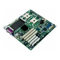
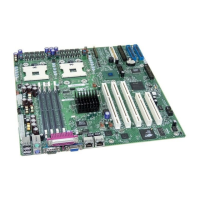
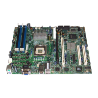
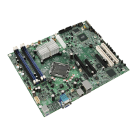
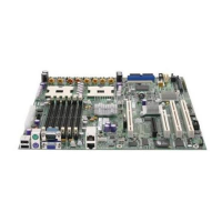
PCI Slot 6 (PCI-X 133) is near the center of the board, Slot 5 and 6 are PCI-Express, slot 4 is
PVIC 32/33, and slots 1 & 2 are both PCI-X64/100 based. Slots 1 & 2 are nearest to the edge
of the board.
 Loading...
