Platform Management ArchitectureIntel® Server Board SE7520BD2 Technical Product Specification
106 Revision 1.3
Sensor Name
Sensor
#
Sensor
Type
Event /
Reading
Type
Event Offset
Triggers
Assert /
Deassert
Readable
Value/Offsets
Event Data
PEF
Action
SDR
Record
Type
Chassis Identify
Button
26h
Button
14h
Generic
03h
Sate
Deasserted
State Assert
As & De – Trig Offset
ID LED
Action
02
Proc1 Fan 27h
Fan
04h
Threshold
01h
[u,l][ nr, c,nc] As & De Analog R, T
Fault LED
Action
01
Proc2 Fan 28h
Fan
04h
Threshold
01h
[u,l][ nr, c,nc] As & De Analog R, T
Fault LED
Action
01
Proc1 Core temp 29h
Temp
01h
Threshold
01h
[u,l][ nr, c,nc] As & De Analog R, T
Fault LED
Action
01
Proc2 Core temp 2Ah
Temp
01h
Threshold
01h
[u,l][ nr, c,nc] As & De Analog R, T
Fault LED
Action
01
CPU
Configuration
Error
2Bh
Processor
07h
Generic
03h
State
Asserted
As & De Discrete R, T
Fault LED
Action
02
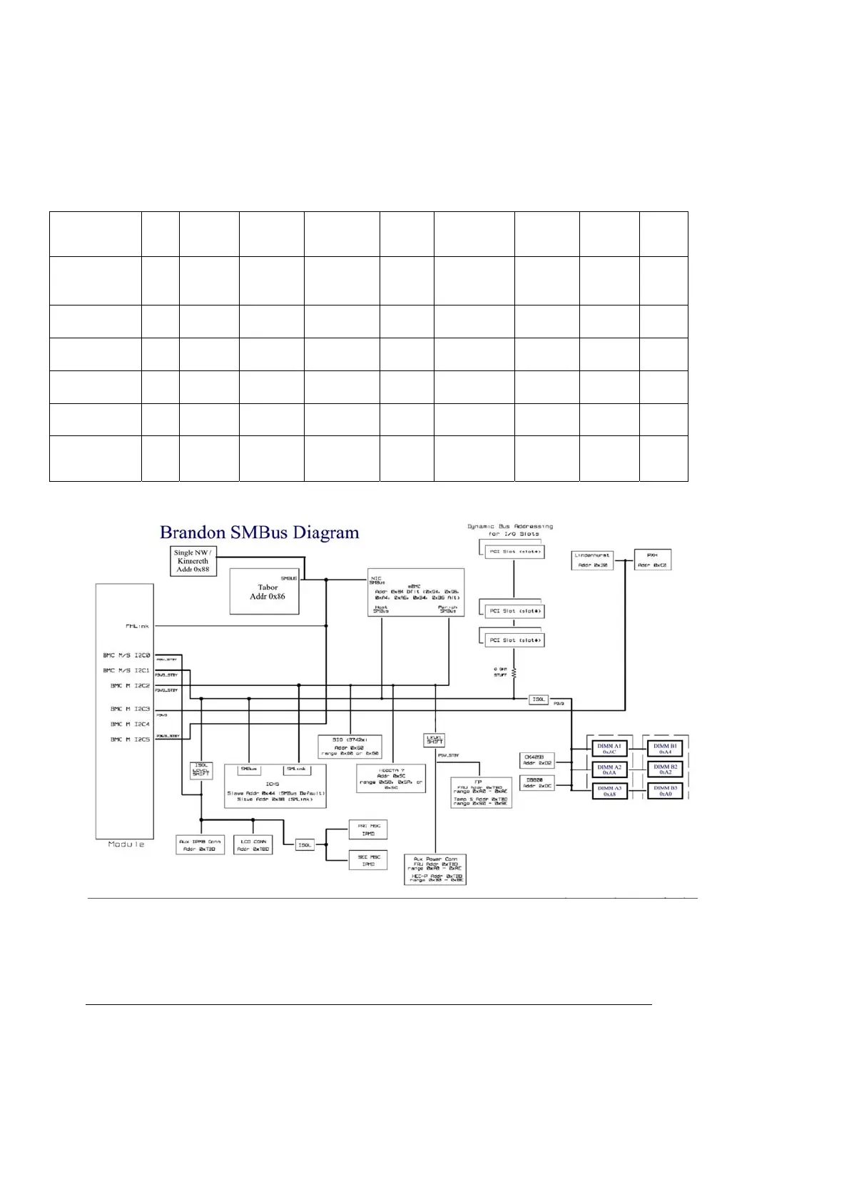
4.5 Server Management Block Diagram
4.6 Management Buses and Connectors
The server board interfaces to the server/system management controller (SMC) via a system
management connector. When a system management card is installed, the features associated
with system management will be through the installed add-in SM card. When not installed, there

 Loading...


