2 - 5
Section E
Hydraulics
9803/3280
Section E
2 - 5
Issue 3*
Technical Data
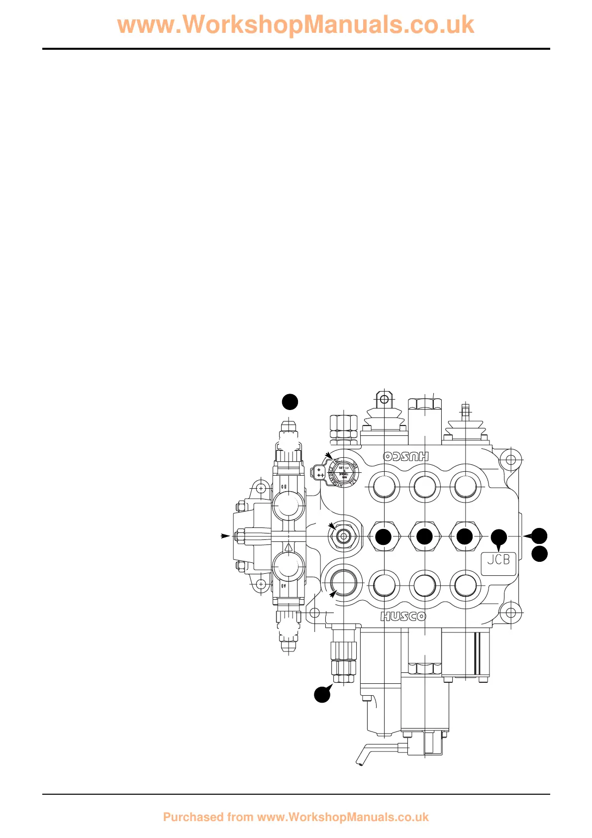
Component Key:
1 Arms lift service
2 Shovel service
3 Auxiliary (optional)
4 Pump section 1 - inlet
5 Pump section 2 - inlet
6 Pressure test port
7 Unloader Assembly
8 Unloader solenoid
9 Auxiliary relief valve
10 Tank port
11 High pressure carry-over (HPCO) port
12 Service ports
13 Load hold check valve assemblies
14 Main relief valve (MRV)
15 Bolt on auxiliary spool
16 Data plate
bar kgf/cm
2
lbf/in
2
Main Relief Valve (M.R.V.) 227 - 231 232 - 235 3300 - 3350
Unloader Valve 203 - 207 207 - 211 2950 - 3000
Auxiliary Relief Valves (A.R.V.)
Loader
Shovel Ram Head Side 172 - 175 175 - 179 2500 - 2550
Shovel Ram Rod side 308 - 312 315 - 318 4475 - 4525
Bolt on Auxiliary Spool (extending dipper, if fitted)
Top relief valve 136 - 140 139 - 142 1975 - 2025
Bottom relief valve 205 - 208 209 - 212 2975 - 3025
Note: Instructions for pressure testing and adjustment are described in Service Procedures, Loader Valve - Pressure
Testing.
Relief Valve Pressures
Loader Valve - Precision Control (Servo)
(Machines up to serial no. 931159)
1
7
2
3
4
5
6
9
9
9
@
@
@
@
@
@
8
9
@
@
10
16
14
11
13
13 13
15
A402480
*
 Loading...