EasyManuals Logo
Home>jcb>Other>214

jcb 214 Service Manual

jcb 214
890 pages
To Next Page IconTo Next Page
To Previous Page IconTo Previous Page
Page #839 background imageLoading...
Page #839 background image
3 - 1
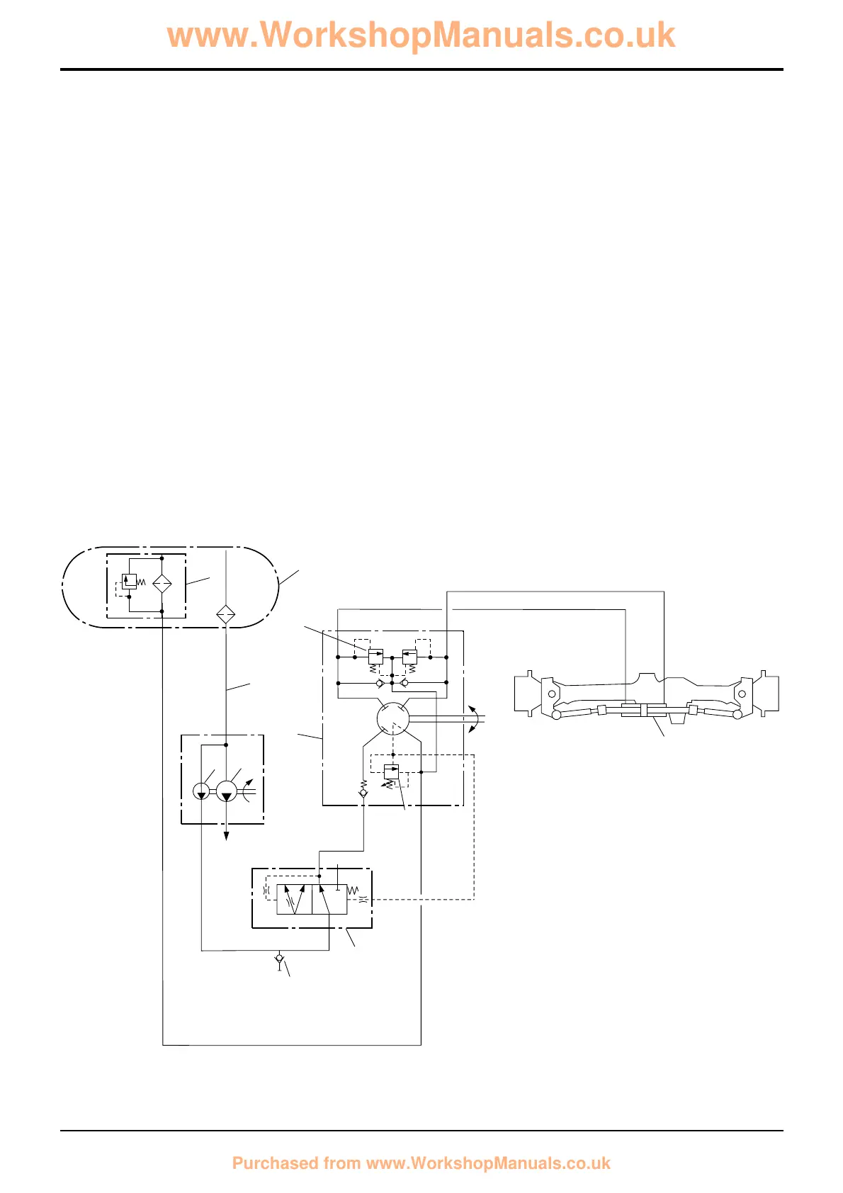
2 Wheel Steer Machines
Steer System Schematics
Component Key:
P1 Pump, Main Section
P2 Pump, Secondary Section
P2A Pressure Test Point
S Suction Line
T Tank
6 In-tank Filter
7 Priority Valve
10 Front Power Track Rod Ram
42 Steer Unit
43 Shock Valve
44 Steer Unit Relief Valve
Note: Hydraulic component port identification letters are
shown in parenthesis, e.g. (LS). The same letters will be
stamped on the actual component.
Section H Steering
9803/3280
Section H
3 - 1
Issue 1
Basic System Operation
S
6
P2A
7
P2
P1
44
42
43
(R)
(L)
(P)
(T)
(LS)
(LS)
(CF)
(P)
10
T
(EF)
A263860
www.WorkshopManuals.co.uk
Purchased from www.WorkshopManuals.co.uk

Table of Contents

Questions and Answers:

Question and Answer IconNeed help?

Do you have a question about the jcb 214 and is the answer not in the manual?

jcb 214 Specifications

General IconGeneral
Brandjcb
Model214
CategoryOther
LanguageEnglish

Related product manuals