Powershift Gearbox - 6 Speed
Electrical Connections - Wires and Connectors
Schematics are divided into 2 parts: Input Controls and
Gearbox Solenoid Actuation.
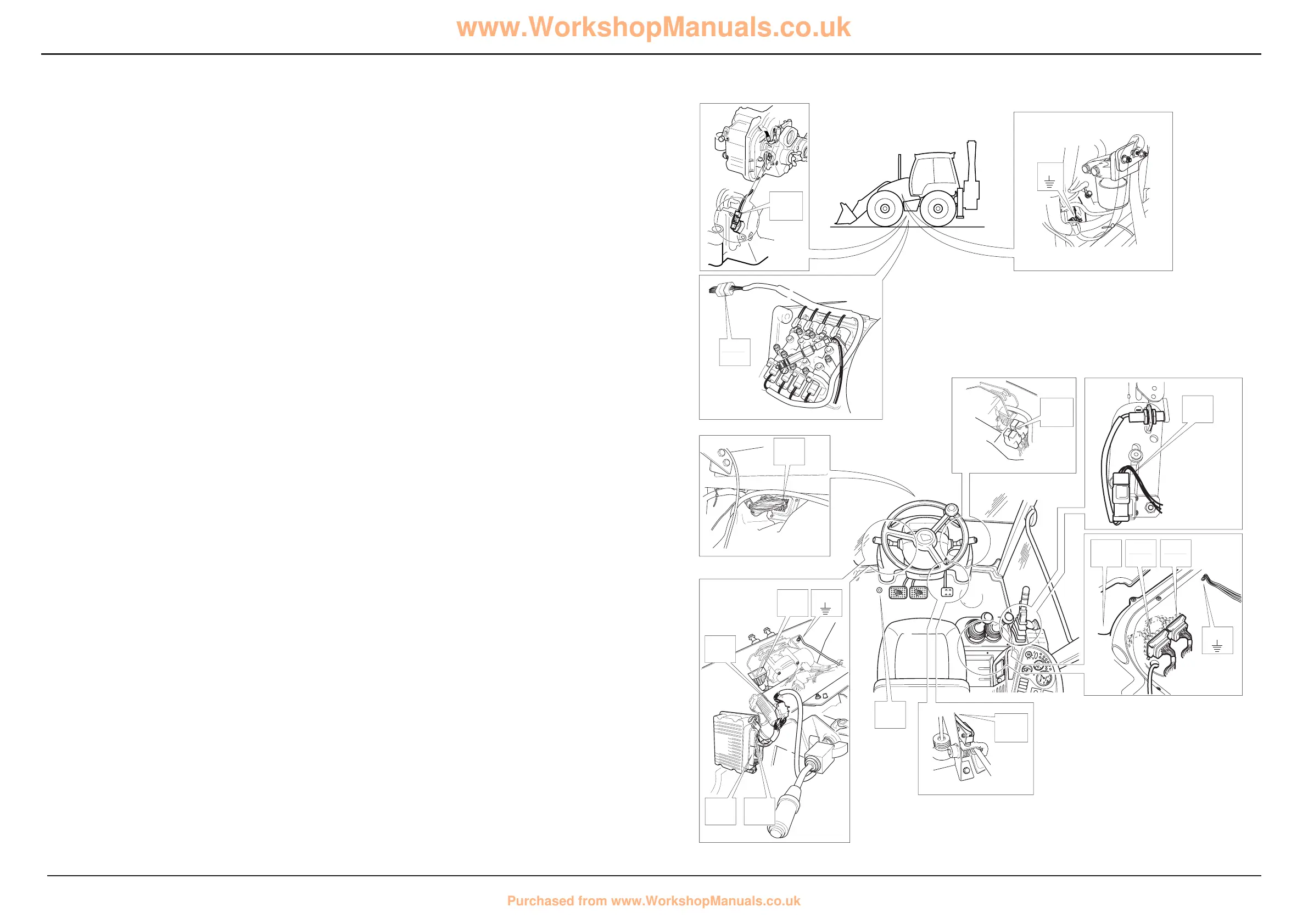
On the electrical diagram opposite the electrical connectors
(example, FA to LA) are shown looking on the mating face of
each connector when they are disconnected.
The wire numbers and colours, where appropriate, are
shown as an aid to identification whilst fault finding.
Before fault finding make sure that you understand how the
the electrical circuits work. The most effective method of
fault finding is by means of ShiftMaster Daignostics software
and a laptop PC, see Service Procedures, Powershift
Gearbox - 6 speed, ShiftMaster Diagnostis - User Guide.
Having identified a faulty system, use the schematics to
identify the relevant wires and connectors, continuity checks
can then be carried out using a multimeter. Gearbox
solenoid coils can be checked for the correct resistance
value as given in Technical Data. See Service Procedures,
Electrical Testing Methods for more details.
Input Controls
For gearbox solenoid actuation see subsequent pages.
Component Key (Input controls):
The following key identifies the component connectors on
the opposite diagrams. Note that the wires coloured red
show the electrical ‘live feed’ to the column gear lever and
gearbox E.C.U..
h1 Harness - 721/10937 Front console
h2 Harness - 721/10971 Link
h3 Harness - 721/10970 Side console
h4 Harness - 721/10935 Engine/mainframe
h5 Harness - 721/10941 Transmission
Note: For harness drawings see Section C.
Connectors (h1)
FA h1 î h2
FB1 Earth point
FG Transmission dump relay
Note: Identify dump relay FG by locating wire 1873 at pin 2
of the corresponding relay base.
FL Column gear lever
GB E.C.U. connector A
GC E.C.U. connector B
GG Throttle switch
Connectors (h2)
LA h2
î h1
LB h2 î h3
LC h2 î h5
LE Kick down switch
Connectors (h3)
CA h3 î h4
CB h3 î h2
CM Park brake warning light relay
CCA Fuses
DR2 Earth point
DZ Park brake relay
DW Park brake switch
EA Immobiliser
EAB Link - immobiliser (if immobiliser is not fitted)
Connectors (h4)
NH h4
î h3
NG Transmission dump switch
MB1 Earth point
Splices (h1)
SA
SC
SF
SJ
SL
SS
Splices h2
SB
SC
Splices h3
DW
TF
Splices h4
SA
Splices h5
SA
Earth Points
Faults may be caused by poor earth connections. Although
earth connections are shown opposite, it must be
remembered that the cab assembly is earthed via further
earth strap and cable connections. For details of these
connections see Section C, Machine Earth Connections.
 Loading...